You are looking at the website for a prior offering of this course. Here is the current website:
Contents
- Design Project #4 (Drone)
- Design Project #3 (Spacecraft with star tracker)
- Design Project #2 (Differential-drive robot in artificial gravity)
- Design Project #1 (CMG)
Design Project #4 (Drone)
The system
The fourth project that you will complete this semester is to design, implement, and test a controller that enables a quadrotor - aka “the drone” - to race through rings from start to finish without crashing:
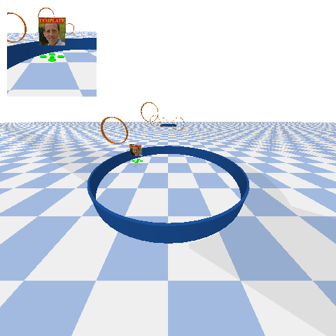
In particular, your drone will be racing with other drones. You will need to take care not to run into these other drones, as collisions may cause drones to crash.
The motion of each drone is governed by ordinary differential equations with the following form:
\[\begin{bmatrix} \dot{p}_x \\ \dot{p}_y \\ \dot{p}_z \\ \dot{\psi} \\ \dot{\theta} \\ \dot{\phi} \\ \dot{v}_x \\ \dot{v}_y \\ \dot{v}_z \\ \dot{w}_x \\ \dot{w}_y \\ \dot{w}_z \end{bmatrix} = f\left(p_x, p_y, p_z, \psi, \theta, \phi, v_x, v_y, v_z, w_x, w_y, w_z, \tau_x, \tau_y, \tau_z, f_z \right)\]In these equations:
- $p_x$ is the $x$ position (m)
- $p_y$ is the $y$ position (m)
- $p_z$ is the $z$ position (m)
- $\psi$ is the yaw angle (rad)
- $\theta$ is the pitch angle (rad)
- $\phi$ is the roll angle (rad)
- $v_x$ is the linear velocity along the body-fixed $x$ axis (m/s)
- $v_y$ is the linear velocity along the body-fixed $y$ axis (m/s)
- $v_z$ is the linear velocity along the body-fixed $z$ axis (m/s)
- $w_x$ is the angular velocity about the body-fixed $x$ axis (rad/s), which points forward
- $w_y$ is the angular velocity about the body-fixed $y$ axis (rad/s), which points left
- $w_z$ is the angular velocity about the body-fixed $z$ axis (rad/s), which points up
- $\tau_x$ is the net torque about the body-fixed $x$ axis ($N\cdot\text{m}$)
- $\tau_y$ is the net torque about the body-fixed $y$ axis ($N\cdot\text{m}$)
- $\tau_z$ is the net torque about the body-fixed $z$ axis ($N\cdot\text{m}$)
- $f_z$ is the net force along the body-fixed $z$ axis ($N$)
A symbolic description of these equations of motion is provided with the project code.
The actuators that produce the net torques $\tau_x, \tau_y, \tau_z$ and net force $f_z$ are the four rotors on the drone, each of which is driven by an electric motor. These rotors can spin in only one direction, and have minimum and maximum speeds. These bounds limit the torques and forces that can actually be produced. These limits are more complicated than simple minimums and maximums. Here are two ways to get a sense for what these limits are:
-
Call the function
(
  tau_x,
  tau_y,
  tau_z,
  f_z,
) = simulator.enforce_motor_limits(
  tau_x_cmd,
  tau_y_cmd,
  tau_z_cmd,
  f_z_cmd,
)
to find the torques and forces that would actually be applied for given torque and force commands. Note that this function cannot be called from within your controller code — it can only be called from elsewhere in your notebook, for the purpose of testing.
-
Use your data from simulation to plot both the torque and force commands as well as the torques and forces that are actually applied. An example is provided in the template notebook.
Ask if you want more details about the mapping from commanded to actual forces and torques.
Sensors provide a noisy measurement of the following things:
- the position of the drone ($p_x, p_y, p_z$)
- the yaw angle of the drone ($\psi$)
- the position of the center of the next ring that the drone needs to pass through ($p_{\text{ring},x}, p_{\text{ring},y}, p_{\text{ring},z}$), as well as an indication (“true” or “false”) of whether or not this is the last ring, a.k.a. the “finish”
- the position of all other drones
The code provided here simulates the motion of this system (DroneDemo) and also derives the equations of motion in symbolic form (DeriveEOM).
The goal is to race as fast as possible from the start ring to the goal ring, passing through all the rings in between.
Your tasks
The focus of your analysis this time will be on identifying and diagnosing failures. In this context, a “failure” is anything that causes your drone not to reach the finish ring. There are many reasons why a particular control design might lead to failure. Your job as a control engineer is to uncover and address these sources of failure. At minimum, you should do the following two things for your final control design:
-
Identify as many failures as possible.
-
Diagnose each failure, saying why you think it happened and providing evidence to support your claim.
It is often helpful to put failures into categories — that is, to identify and diagnose types of failures, and to use particular failures as a way to illustrate each type.
Remember that you have practice in doing rigorous data collection, analysis, and visualization (the focus of the third design project). This can help a lot in identifying and diagnosing failures.
You may, of course, be tempted to eliminate failures after you find them, by making some change to your control design. This is exactly the right thing to do, but remember that after you make a change, you’ll have to repeat (completely) your analysis of failure.
Things you need to do
Do the following thing to clarify your goal:
- Define a requirement and a verification, just as you did in the second design project.
Do the following things to produce a control design:
- Linearize the dynamic model and the sensor model.
- Show that the linearized system is both controllable and observable.
- Design a stable controller and a stable observer.
- Add trajectory tracking to enable movement between rings.
- Implement the controller and observer (with trajectory tracking) and test them in simulation.
Do the following things to evaluate your control design:
- Identify and diagnose as many sources of failure as you can find.
- Create at least four figures of aggregate results from at least 100 simulations:
- Show how well your controller is working (e.g., with a histogram of error between actual position and desired position).
- Show how well your observer is working (e.g., with a histogram of error between estimated position and actual position).
- Show how fast your drone completes the race (e.g., with a histogram of completion times). You may also want to show how likely it is that your drone completes the race at all, without failure.
- Show how long it takes your controller to run (e.g., with a histogram of computation times). This will help you avoid being disqualified in the race.
Do the following thing to compete in the race:
- Submit a control design that runs without being disqualified (i.e., it does not raise an exception, it does not print any debug text, and it does not exceed limits on computation time).
An exceptional response to this project would go beyond minimum requirements and consider one or more questions like the following:
- Can you think of a way to avoid collision with other drones?
- How do your results change with different amounts of sensor noise?
- Is there a tradeoff between the completion time and the likelihood you complete the race at all?
There are many other opportunities — let us know what strikes you as interesting.
Your deliverables
Draft report with theory (by 11:59pm on Friday, April 15)
Submit a first draft of your report (see below for guidelines) that includes, at minimum, a complete “Theory” section. This draft must also include the appendix with your log of all work done so far by each group member.
Upload it to the DP4 Draft 1 assignment on Gradescope. This is a group assignment, so please be sure to add your partner to your submission.
Draft report with results (by 11:59pm on Friday, April 22)
Submit a second draft of your report (see below for guidelines) that includes, at minimum, a complete “Experimental methods” section and a complete “Results and discussion” section. This draft must also include the appendix with your log of all work done so far by each group member.
Upload it to the DP4 Draft 2 assignment on Gradescope. This is a group assignment, so please be sure to add your partner to your submission.
Contest entry (by 5:00pm on Tuesday, May 3)
There will be an opportunity to race with your friends in a friendly contest on the last day of class (Wednesday, May 4). The same project code that you are using for the purpose of control design and simulation will be used to run each race in this contest. To enter the race, your team must upload exactly two files to the “DP04-Race-Submissions” Box folder:
netid.py, with a completely self-contained implementation of your control design, in the format specified by 04_drone/students/template.py.netid.png, with an image (keep it professional) that can be used to distinguish your drone from others.
You must, of course, replace netid with your own netid. Please use all lowercase.
Please submit only one pair of files - with the NetID of only one group member - for each group. Your submission will automatically be associated with all members of your group.
All groups are required to entire the race! Your submission will be assessed based on whether or not it satisfies three conditions:
- It must not raise an exception (i.e., throw an error).
- It must not print anything to
stdout(i.e., runprintstatements). - It must not exceed limits on computation time (5 seconds for module load, 1 second for
__init__, 1 second forreset, and1e-3seconds forrun).
Your submission will not be assessed based on whether or not it wins the race.
Final report (by 11:59pm on Tuesday, May 3)
This report will satisfy the following requirements:
- It must be a single PDF document that conforms to the guidelines for Preparation of Papers for AIAA Technical Conferences. In particular, you must use either the Word or LaTeX manuscript template.
- It must have a descriptive title that begins with “DP4” (e.g., “DP4: Control of a drone”).
- It must have a list of author names and affiliations.
- It must contain the following sections:
- Abstract. Summarize your entire report in one short paragraph.
- Nomenclature. List all symbols used in your report, with units.
- Introduction. Prepare the reader to understand the rest of your report and how it fits within a broader context.
- Theory. Derive a model and do control design.
- Experimental methods. Describe the experiments you performed in simulation in enough detail that they could be understood and repeated by a colleague.
- Results and discussion. Show the results of your experiments in simulation (e.g., with plots and tables) and discuss the extent to which they validate your control design.
- Conclusion. Summarize key conclusions and identify ways that others could improve or build upon your work.
- Acknowledgements. Thank anyone outside your group with whom you discussed this project and clearly describe what you are thanking them for.
- References. Cite any sources, including the work of your colleagues.
- Appendix. See below.
- It must be a maximum of 6 pages.
The appendix, which does not count against your page limit, must have a table (with as many rows as necessary) that logs all of the work done by each group member on the project:
| Day | Task | Person or People |
|---|---|---|
Submit your report by uploading it to the DP4 Report assignment on Gradescope. This is a group assignment, so please be sure to add your partner to your submission.
Final video (by 11:59pm on Tuesday, May 3)
This video will satisfy the following requirements:
- It must be 70 seconds in length.
- The first and last 5 seconds must include text with a descriptive title (the same title as your report), your names, and the following words somewhere in some order:
- AE353: Aerospace Control Systems
- Spring 2022
- Department of Aerospace Engineering
- University of Illinois at Urbana-Champaign
- The middle 60 seconds must clearly communicate what you did, why you did it, how you did it, and what the results were.
- It must show at least one simulation of your working control system.
- It must stay professional (use good sense, please).
Submit your video by uploading it to the AE353 (Spring 2022) Project Videos channel on Illinois Media Space. Please take care to do the following:
- Use the same descriptive title as your report, appended with your names in parentheses — for example, “DP4: Control of a drone (Tim Bretl and Jacob Kraft)”.
- Add the tag
dp4(a lower case “dp” followed by the number “4”), so viewers can filter by project number.
You are welcome to resubmit your video at any time before the deadline. To do so, please “Edit” your existing video and then do “Replace Media”. Please do not create a whole new submission.
We realize that 60 seconds is short! Think carefully about what to include (what to show and what to say) and anticipate the need for multiple “takes” and for time spent editing.
Final code (by 11:59pm on Tuesday, May 3)
This code will satisfy the following requirements:
- It must be a single jupyter notebook (with the extension
.ipynb) that, if placed in theprojects/04_dronedirectory and run from start to finish, would reproduce all of the results that you show in your report. - It must not rely on any dependencies other than those associated with the
ae353conda environment. - It must be organized and clearly documented, with a mix of markdown cells and inline comments.
Submit your code by uploading it to the DP4 Code assignment on Gradescope. This is a group assignment, so please be sure to add your partner to your submission.
Evaluation
Your project grade will be weighted as follows:
- (10%) Draft report with theory
- (10%) Draft report with results
- (50%) Final report
- (20%) Final video
- (5%) Final code
- (5%) Race submission
Rubrics will be discussed in class.
Frequently asked questions
May I watch videos that are submitted by other students?
Yes. All videos will be available in the AE353 (Spring 2022) Project Videos channel on Illinois Media Space as soon as they are submitted by your colleagues (see the Video deliverable). You may watch these videos whenever you want, even before you submit your own.
If you are inspired by a video, or if watching a video strongly influences the way you proceed with your own design project, then you must acknowledge and cite this video in your report (and in your own video, if appropriate). Failure to do so would be considered plagiarism.
How do I get started?
The first thing you should do is follow the instructions to download and run course code, verify that you can run the simulation, and mess around a little bit with different actuator commands (e.g., constant wheel torques) to get a sense for how the system responds.
After that, if you have read the entire project description and are not sure how to proceed, then take your best guess and ask a question on Campuswire. Improving your ability to get unstuck by asking a good question is an explicit goal of this course.
Design Project #3 (Spacecraft with star tracker)
The system
The third project that you will complete this semester is to design, implement, and test a controller that enables a spacecraft to maintain a fixed orientation, as pictured below:
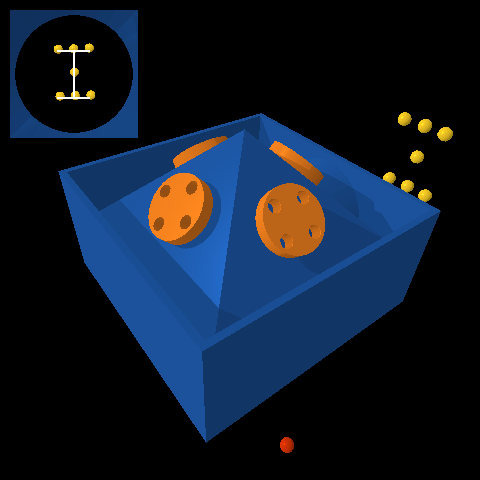
This spacecraft (blue) has four reaction wheels (orange) that are arranged in a pyramid.
The actuators are motors that allow a torque to be applied by the spacecraft to each wheel, up to a maximum of $\pm 1\;\text{N}\cdot\text{m}$. The rotational motion of the system is governed by ordinary differential equations with the following form:
\[\begin{bmatrix} \dot{\psi} \\ \dot{\theta} \\ \dot{\phi} \\ \dot{w_x} \\ \dot{w_y} \\ \dot{w_z} \end{bmatrix} = f\left(\psi, \theta, \phi, w_x, w_y, w_z, \tau_1, \tau_2, \tau_3, \tau_4\right)\]In these equations:
- $\psi$ is the yaw angle (rad)
- $\phi$ is the roll angle (rad)
- $\theta$ is the pitch angle (rad)
- $w_x$ is the angular velocity about the body-fixed $x$ axis (rad/s), which points forward
- $w_y$ is the angular velocity about the body-fixed $y$ axis (rad/s), which points left
- $w_z$ is the angular velocity about the body-fixed $z$ axis (rad/s), which points up
- $\tau_1$ is the torque applied to wheel 1 ($N\cdot\text{m}$), which is in front
- $\tau_2$ is the torque applied to wheel 2 ($N\cdot\text{m}$), which is in back
- $\tau_3$ is the torque applied to wheel 3 ($N\cdot\text{m}$), which is on the left
- $\tau_4$ is the torque applied to wheel 4 ($N\cdot\text{m}$), which is on the right
A symbolic description of these equations of motion is provided with the project code.
The sensor is a star tracker. It measures the position (in an image) of each star in its field of view. This measurement has the following form for each star:
\[\begin{bmatrix} y_\text{star} \\ z_\text{star} \end{bmatrix} = g(\psi, \theta, \phi, \alpha, \delta)\]You will already recognize the yaw, pitch, and roll angles in this equation. The other variables are:
- $\alpha$ is the right ascension (rad) of the star
- $\delta$ is the declination (rad) of the star
Again, a symbolic description of this equation is provided with the project code. There are seven stars in total — you can find the parameters $\alpha$ and $\delta$ for each one in the SpacecraftDemo template.
The code provided here simulates the motion of this system (SpacecraftDemo) and also derives both the equations of motion and the sensor model in symbolic form (DeriveEOM).
The goal is to keep the spacecraft close to zero yaw, pitch, and roll for as long as possible despite noisy sensor measurements and a shooting star (!?!).
Why do I say “for as long as possible?” Because the simulator will quit and the spacecraft mission will be declared over when one of two conditions are met:
- Any star leaves the star tracker’s field of view.
- Any reaction wheel has angular velocity that exceeds $\pm 50\;\text{rad}/\text{s}$.
Since you have no way to do momentum dumping (or… do you?), it is inevitable that one of the wheels will eventually spin too fast. Just try to hang on as long as you can.
Your tasks
The focus of your analysis this time will be on data collection. The initial conditions, the sensor measurements, and the disturbances are random. So, for a given control design, your results will vary (perhaps significantly). It is not enough to look at the results of one simulation—you will have to look at the results of many simulations. At minimum, for each design you consider, you should do the following:
- Collect data from at least 100 simulations that run until failure (i.e., with a very large
max_time). - Plot a histogram of the time until failure across all simulations.
- Plot a histogram of the root-mean-square error (RMSE) in yaw, pitch, and roll angles across all simulations.
Remember that the simulation code provides an option to turn the display off, which can speed up data collection a lot.
Things you need to do
Please do the following things:
- Define a requirement and a verification, just as you did in the second design project.
- Linearize the equations of motion and the sensor model.
- Show that the linearized system is both controllable and observable.
- Design a stable controller and a stable observer.
- Implement both the controller and observer and test them in simulation.
- Follow the instructions you wrote to verify that your requirement is (or is not) satisfied.
- Include at least one figure of aggregate results (e.g., a histogram).
- Include at least one figure that provides evidence the observer is working (e.g., a plot of error in the state estimate as a function of time).
An exceptional response to this project would go beyond minimum requirements and consider one or more questions like the following:
- How do your results change with different amounts of sensor noise?
- How do your results change with a different number or arrangement of stars? (This is something you can choose, if you want.)
- Is there a tradeoff between “time until failure” and “RMSE in yaw, pitch, and roll” or can both measures of performance be improved together?
There are many other opportunities — let us know what strikes you as interesting.
Your deliverables
Draft report with theory (by 11:59pm on Friday, March 25)
Submit a first draft of your report (see below for guidelines) that includes, at minimum, a complete “Theory” section. This draft must also include the appendix with your log of all work done so far by each group member.
Upload it to the DP3 Draft 1 assignment on Gradescope. This is a group assignment, so please be sure to add your partner to your submission.
Draft report with results (by 11:59pm on Friday, April 1)
Submit a second draft of your report (see below for guidelines) that includes, at minimum, a complete “Experimental methods” section and a complete “Results and discussion” section. This draft must also include the appendix with your log of all work done so far by each group member.
Upload it to the DP3 Draft 2 assignment on Gradescope. This is a group assignment, so please be sure to add your partner to your submission.
Final report (by 11:59pm on Friday, April 8)
This report will satisfy the following requirements:
- It must be a single PDF document that conforms to the guidelines for Preparation of Papers for AIAA Technical Conferences. In particular, you must use either the Word or LaTeX manuscript template.
- It must have a descriptive title that begins with “DP3” (e.g., “DP3: Control of a spacecraft with reaction wheels and a star tracker”).
- It must have a list of author names and affiliations.
- It must contain the following sections:
- Abstract. Summarize your entire report in one short paragraph.
- Nomenclature. List all symbols used in your report, with units.
- Introduction. Prepare the reader to understand the rest of your report and how it fits within a broader context.
- Theory. Derive a model and do control design.
- Experimental methods. Describe the experiments you performed in simulation in enough detail that they could be understood and repeated by a colleague.
- Results and discussion. Show the results of your experiments in simulation (e.g., with plots and tables) and discuss the extent to which they validate your control design.
- Conclusion. Summarize key conclusions and identify ways that others could improve or build upon your work.
- Acknowledgements. Thank anyone outside your group with whom you discussed this project and clearly describe what you are thanking them for.
- References. Cite any sources, including the work of your colleagues.
- Appendix. See below.
- It must be a maximum of 6 pages.
The appendix, which does not count against your page limit, must have a table (with as many rows as necessary) that logs all of the work done by each group member on the project:
| Day | Task | Person or People |
|---|---|---|
Submit your report by uploading it to the DP3 Report assignment on Gradescope. This is a group assignment, so please be sure to add your partner to your submission.
Final video (by 11:59pm on Friday, April 8)
This video will satisfy the following requirements:
- It must be 70 seconds in length.
- The first and last 5 seconds must include text with a descriptive title (the same title as your report), your names, and the following words somewhere in some order:
- AE353: Aerospace Control Systems
- Spring 2022
- Department of Aerospace Engineering
- University of Illinois at Urbana-Champaign
- The middle 60 seconds must clearly communicate what you did, why you did it, how you did it, and what the results were.
- It must show at least one simulation of your working control system.
- It must stay professional (use good sense, please).
Submit your video by uploading it to the AE353 (Spring 2022) Project Videos channel on Illinois Media Space. Please take care to do the following:
- Use the same descriptive title as your report, appended with your names in parentheses — for example, “DP3: Control of a spacecraft with reaction wheels and a star tracker (Tim Bretl and Jacob Kraft)”.
- Add the tag
dp3(a lower case “dp” followed by the number “3”), so viewers can filter by project number.
You are welcome to resubmit your video at any time before the deadline. To do so, please “Edit” your existing video and then do “Replace Media”. Please do not create a whole new submission.
We realize that 60 seconds is short! Think carefully about what to include (what to show and what to say) and anticipate the need for multiple “takes” and for time spent editing.
Final code (by 11:59pm on Friday, April 8)
This code will satisfy the following requirements:
- It must be a single jupyter notebook (with the extension
.ipynb) that, if placed in theprojects/03_spacecraftdirectory and run from start to finish, would reproduce all of the results that you show in your report. - It must not rely on any dependencies other than those associated with the
ae353conda environment. - It must be organized and clearly documented, with a mix of markdown cells and inline comments.
Submit your code by uploading it to the DP3 Code assignment on Gradescope. This is a group assignment, so please be sure to add your partner to your submission.
Evaluation
Your project grade will be weighted as follows:
- (10%) Draft report with theory
- (10%) Draft report with results
- (50%) Final report
- (20%) Final video
- (10%) Final code
Rubrics will be discussed in class.
Frequently asked questions
May I watch videos that are submitted by other students?
Yes. All videos will be available in the AE353 (Spring 2022) Project Videos channel on Illinois Media Space as soon as they are submitted by your colleagues (see the Video deliverable). You may watch these videos whenever you want, even before you submit your own.
If you are inspired by a video, or if watching a video strongly influences the way you proceed with your own design project, then you must acknowledge and cite this video in your report (and in your own video, if appropriate). Failure to do so would be considered plagiarism.
How do I get started?
The first thing you should do is follow the instructions to download and run course code, verify that you can run the simulation, and mess around a little bit with different actuator commands (e.g., constant wheel torques) to get a sense for how the system responds.
After that, if you have read the entire project description and are not sure how to proceed, then take your best guess and ask a question on Campuswire. Improving your ability to get unstuck by asking a good question is an explicit goal of this course.
Design Project #2 (Differential-drive robot in artificial gravity)
The system
The second project that you will complete this semester is to design, implement, and test a controller that enables a differential-drive robot to move quickly around the inside of a rotating space station under artificial gravity, as pictured below:
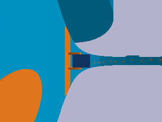
This robot consists of a chassis (dark blue), a left wheel (orange), and a right wheel (also orange). It is called “differential-drive” because two separate motors allow a different torque to be applied to the left wheel and the right wheel:
- If both wheels are rotating forward at the same rate, the robot moves straight.
- If the left wheel is rotating forward faster than the right wheel, the robot turns right.
- If the right wheel is rotating forward faster than the left wheel, the robot turns left.
This is a common design choice for mobile robots. For example, NASA used it in a prototype of Robonaut. You can read more about the reasons why in the textbook Introduction to Autonomous Mobile Robots, Second Edition (Siegward, Nourbakhsh, and Scaramuzza, 2011), also available online (for free from the library at Illinois and at other academic institutions). The two-wheeled, differential-drive design has, of course, also been popularized by Segway.
The robot is under the influence of artificial gravity induced by the rotation of the space station. In particular, if the station is rotating with angular velocity $\omega_\text{station}$ and if the radius of the station (the distance from the center of rotation to its inner surface) is $r_\text{station}$, then the robot will “feel” as if it were being pulled outward by gravity with acceleration equal to the centripetal acceleration
\[g = \omega_\text{station}^2 / r_\text{station}.\]If we assume (incorrectly) that the inside of the space station is flat and not curved upward, then the motion of the system is governed by ordinary differential equations with the following form (see Studies of Systems with Nonholonomic Constraints: the Segway and the Chaplygin Sleigh (Tuttle, 2014) for a derivation):
\[\begin{bmatrix} \dot{e}_\text{lateral} \\ \dot{e}_\text{heading} \\ \dot{v} \\ \dot{w} \\ \ddot{\theta} \end{bmatrix} = f(e_\text{lateral}, e_\text{heading}, v, w, \theta, \dot{\theta}, \tau_R, \tau_L)\]The details of the function $f$ get a little complicated:
\[\begin{bmatrix}v \sin{\left(e_\text{heading} \right)}\\w\\- \frac{2400 \tau_{L} + 2400 \tau_{R} + 2808 \left(\dot{\theta}^{2} + w^{2}\right) \sin{\left(\theta \right)} + 65 \left(50 \tau_{L} + 50 \tau_{R} - 39 w^{2} \sin{\left(2 \theta \right)} - 900 \sin{\left(\theta \right)}\right) \cos{\left(\theta \right)}}{11700 \cos^{2}{\left(\theta \right)} - 12168}\\\frac{32 \left(- 875 \tau_{L} + 875 \tau_{R} - 1443 \dot{\theta} w \sin{\left(2 \theta \right)} - 2925 v w \sin{\left(\theta \right)}\right)}{13 \left(3120 \sin^{2}{\left(\theta \right)} + 2051\right)}\\\frac{5 \left(8450 \tau_{L} + 8450 \tau_{R} - 6591 w^{2} \sin{\left(2 \theta \right)} + 60 \left(100 \tau_{L} + 100 \tau_{R} + 117 \left(\dot{\theta}^{2} + w^{2}\right) \sin{\left(\theta \right)}\right) \cos{\left(\theta \right)} - 152100 \sin{\left(\theta \right)}\right)}{1404 \left(25 \cos^{2}{\left(\theta \right)} - 26\right)}\end{bmatrix}\]So, you are encouraged to use the symbolic description of these equations of motion that is provided with the project code — there is no need to transcribe them yourself.
In these equations:
- $e_\text{lateral}$ is the lateral error (m), or the distance from the center of the robot (more precisely, from the wheel center, or the point halfway between its two wheels) to the centerline of the station ring — if this quantity is positive, then the robot is too far to the left; if this quantity is negative, then the robot is too far to the right
- $e_\text{heading}$ is the heading error (rad), or the difference between the orientation of the robot and the direction of the station ring — if this quantity is positive, then the robot is pointing to far to the left; if this quantity is negative, then the robot is pointing too far to the right
- $v$ is the forward speed (m/s) — positive means the robot is moving forward
- $w$ is the turning rate (rad/s) — positive means the robot is turning left
- $\theta$ is the pitch angle (rad) — positive means the chassis is pitching forward
- $\dot{\theta}$ is the pitch rate (rad/s)
- $\tau_R$ is the right wheel torque ($N\cdot\text{m}$) applied by the chassis to the right wheel — positive torque will cause this wheel to rotate forward
- $\tau_L$ is the left wheel torque ($N\cdot\text{m}$) applied by the chassis to the left wheel — positive torque will cause this wheel to rotate forward
Sensors provide measurements of all these variables (although these sensors do not provide any information about the station ring — the extent to which it is curving upward, for example). Actuators allow you to choose what torques will be applied, up to a maximum of $\pm 1\;\text{N}\cdot\text{m}$.
The code provided here simulates the motion of this system (SegbotDemo) and also derives the equations of motion in symbolic form (DeriveEOM).
The goal is to get the robot to move as fast as possible around the ring of the space station without causing it to fall off. Beware! There are “bumps” on the inner surface of the space station that may cause your robot to topple if it is going too fast.
Your tasks
In this project, we would like you to be more specific about what you mean by “success” and to provide quantitative evidence supporting the claim that you have (or have not) succeeded. People often think about this in terms of requirements and verifications.
What is a requirement?
A requirement is a property that the system you are designing must have in order to solve your problem (i.e., a thing that needs to get done). A good requirement is quantifiable—it involves a number that must be within a certain range in order to solve your design problem. A good requirement is also both relevant (it must be satisfied—it is not optional) and detailed (it can be read and understood by anyone). Here is an example of a requirement that says what needs to get done but that most engineers would consider unacceptable:
The robot shall move along the ring.
This requirement is not detailed. One way to improve it would be to say what it means to move along the ring:
The wheel center shall remain close to the centerline of the ring.
This requirement is not quantifiable. One way to improve it would be to say how close:
The wheel center shall remain within $\pm 0.1~\text{meters}$ of the ring centerline.
Most engineers would argue that this requirement still needs improvement. How long must the wheel center remain close to the centerline of the ring? Is there an upper bound on the time it must take for the wheel center to get close to the centerline of the ring, assuming it starts somewhere else? Must this requirement be satisfied only if the station is spinning at its nominal rate, or must it be satisfied for any spin rate within certain bounds? Must this requirement be satisfied no matter what the initial conditions are? Or, are there particular operating conditions within which the requirement applies? How fast must the robot be moving along the ring? Must the robot remain upright and moving at all in order to satisfy this requirement, or can it fall over and remain still so long as its wheel center is near the centerline of the ring when it falls? These are examples of reasonable questions that might be asked by an engineer reviewing the requirement. Your task is to define one requirement—that is quantifiable, relevant, and detailed—that makes clear what the system you are designing must do in order for your goal to be achieved.
What is a verification?
A verification is a test that you will perform to make sure that the system you are designing meets a given requirement. A good verification is based on a measurement—it checks that a quantity is in the range specified by the requirement. A good verification also has a set of instructions for how to make the measurement (an experimental protocol) and for how to interpret the results (methods of data analysis and visualization that provide evidence the requirement has been met). Consider the requirement given above (which, as we have said, still needs improvement):
The wheel center shall remain within $\pm 0.1~\text{meters}$ of the ring centerline.
Here is a verification of this requirement that most engineers would consider unacceptable:
The system will be tested in simulation.
This verification is not based on a measurement. Here is a better version that is based on a measurement:
The error between the wheel center and the ring centerline will be found in simulation.
This verification does not include a set of instructions for how to make the measurement or for how to interpret the results. Here is a better version that does include a set of instructions:
PyBullet will be be used to simulate the robot. The data generated by this simulation will be imported into a Jupyter Notebook for analysis with Python. The lateral error — the perpendicular distance between the wheel center and the ring centerline — will be found at each time step. The maximum absolute value of lateral error over all time steps will be reported. If this maximum value is less than $0.1~\text{meters}$, the requirement is met.
Most engineers would argue that this verification still needs improvement. For example, does the simulation generate the same results every time, or is there variation? Just as you saw on your first design project, it seems reasonable to suspect that different initial conditions will produce different results. A reasonable engineer, then, would question whether or not the results of only one simulation would really show that the requirement is met. Many verifications also provide more than just a single number as evidence—for example, they might produce a figure (e.g., a plot of error as a function of time) or some other type of visualization. Your task is to define one verification for your requirement that has a measurement and a set of instructions for how to make the measurement and how to interpret the results.
Things you need to do
Please do the following things:
- Define a requirement and a verification.
- Linearize the equations of motion.
- Show that the linearized system is controllable.
- Design a stable controller.
- Implement this controller and test it in simulation.
- Follow the instructions you wrote to verify that your requirement is (or is not) satisfied.
As always, remember that your controller is not expected to “work” in all cases and that you should try hard to establish limits of performance (i.e., to break your controller). At minimum, you should rigorously vary the initial conditions, as you did in your first design project.
An exceptional response to this project would go beyond minimum requirements and consider one or more questions like the following:
- How does the spin rate of the station (both its sign and magnitude) impact the performance of your controller?
- How fast is it possible to get the robot to move around the ring without it falling off?
- How does performance vary with the choice of speed at which the robot tries to move?
- Does it matter if the robot starts from rest or starts already moving (see
initial_speedin the code)?
There are many other opportunities — let us know what strikes you as interesting.
Your deliverables
Note that final deliverables are due the day before spring break - plan accordingly!
Draft report with theory (by 11:59pm on Friday, February 25)
Submit a first draft of your report (see below for guidelines) that includes, at minimum, a complete “Theory” section. This draft must also include the appendix with your log of all work done so far by each group member.
Upload it to the DP2 Draft 1 assignment on Gradescope. This is a group assignment, so please be sure to add your partner to your submission.
Draft report with results (by 11:59pm on Friday, March 4)
Submit a second draft of your report (see below for guidelines) that includes, at minimum, a complete “Experimental methods” section and a complete “Results and discussion” section. This draft must also include the appendix with your log of all work done so far by each group member.
Upload it to the DP2 Draft 2 assignment on Gradescope. This is a group assignment, so please be sure to add your partner to your submission.
Final report (by 11:59pm on Friday, March 11)
This report will satisfy the following requirements:
- It must be a single PDF document that conforms to the guidelines for Preparation of Papers for AIAA Technical Conferences. In particular, you must use either the Word or LaTeX manuscript template.
- It must have a descriptive title that begins with “DP2” (e.g., “DP2: Control of a differential-drive robot in artificial gravity”).
- It must have a list of author names and affiliations.
- It must contain the following sections:
- Abstract. Summarize your entire report in one short paragraph.
- Nomenclature. List all symbols used in your report, with units.
- Introduction. Prepare the reader to understand the rest of your report and how it fits within a broader context.
- Theory. Derive a model and do control design.
- Experimental methods. Describe the experiments you performed in simulation in enough detail that they could be understood and repeated by a colleague. At minimum, this section should clearly define your requirement and verification.
- Results and discussion. Show the results of your experiments in simulation (e.g., with plots and tables) and discuss the extent to which they validate your control design - in particular, the extent to which they verify your requirement. And as always, remember to focus on establishing limits of performance.
- Conclusion. Summarize key conclusions and identify ways that others could improve or build upon your work.
- Acknowledgements. Thank anyone outside your group with whom you discussed this project and clearly describe what you are thanking them for.
- References. Cite any sources, including the work of your colleagues.
- Appendix. See below.
- It must be a maximum of 6 pages.
The appendix, which does not count against your page limit, must have a table (with as many rows as necessary) that logs all of the work done by each group member on the project:
| Day | Task | Person or People |
|---|---|---|
Submit your report by uploading it to the DP2 Report assignment on Gradescope. This is a group assignment, so please be sure to add your partner to your submission.
Final video (by 11:59pm on Friday, March 11)
This video will satisfy the following requirements:
- It must be 70 seconds in length.
- The first and last 5 seconds must include text with a descriptive title (the same title as your report), your names, and the following words somewhere in some order:
- AE353: Aerospace Control Systems
- Spring 2022
- Department of Aerospace Engineering
- University of Illinois at Urbana-Champaign
- The middle 60 seconds must clearly communicate what you did, why you did it, how you did it, and what the results were.
- It must show at least one simulation of your working control system.
- It must stay professional (use good sense, please).
Submit your video by uploading it to the AE353 (Spring 2022) Project Videos channel on Illinois Media Space. Please take care to do the following:
- Use the same descriptive title as your report, appended with your names in parentheses — for example, “DP2: Control of a differential-drive robot in artificial gravity (Tim Bretl and Jacob Kraft)”.
- Add the tag
dp2(a lower case “DP” followed by the number “1”), so viewers can filter by project number.
You are welcome to resubmit your video at any time before the deadline. To do so, please “Edit” your existing video and then do “Replace Media”. Please do not create a whole new submission.
We realize that 60 seconds is short! Think carefully about what to include (what to show and what to say) and anticipate the need for multiple “takes” and for time spent editing.
Final code (by 11:59pm on Friday, March 11)
This code will satisfy the following requirements:
- It must be a single jupyter notebook (with the extension
.ipynb) that, if placed in theprojects/02_segbotdirectory and run from start to finish, would reproduce all of the results that you show in your report. - It must not rely on any dependencies other than those associated with the
ae353conda environment. - It must be organized and clearly documented, with a mix of markdown cells and inline comments.
Submit your code by uploading it to the DP2 Code assignment on Gradescope. This is a group assignment, so please be sure to add your partner to your submission.
Evaluation
Your project grade will be weighted as follows:
- (10%) Draft report with theory
- (10%) Draft report with results
- (50%) Final report
- (20%) Final video
- (10%) Final code
Rubrics will be discussed in class.
Frequently asked questions
May I watch videos that are submitted by other students?
Yes. All videos will be available in the AE353 (Spring 2022) Project Videos channel on Illinois Media Space as soon as they are submitted by your colleagues (see the Video deliverable). You may watch these videos whenever you want, even before you submit your own.
If you are inspired by a video, or if watching a video strongly influences the way you proceed with your own design project, then you must acknowledge and cite this video in your report (and in your own video, if appropriate). Failure to do so would be considered plagiarism.
How do I get started?
The first thing you should do is follow the instructions to download and run course code, verify that you can run the simulation, and mess around a little bit with different actuator commands (e.g., constant wheel torques) to get a sense for how the system responds. You might want to try a PD controller even before you start doing any analysis.
After that, if you have read the entire project description and are not sure how to proceed, then take your best guess and ask a question on Campuswire. Improving your ability to get unstuck by asking a good question is an explicit goal of this course.
Design Project #1 (CMG)
The system
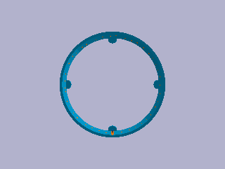
The first project that you will complete this semester is to design, implement, and test a controller that uses a single-gimbal control moment gyroscope (CMG) to reorient a platform in a gravitational field, as pictured below:
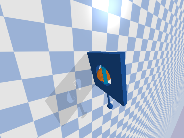
This system has three parts:
- A platform (dark blue) that can rotate freely about its base. Think of this as a spacecraft that is confined to rotate about its pitch axis, as if it were being tested on the ground.
- A gimbal (light blue) that can be driven by a motor to rotate about a perpendicular axis with respect to the platform.
- A rotor (orange) that can be driven by a motor to spin about yet another perpendicular axis with respect to the gimbal.
If the rotor is spun at a high rate, then an “input torque” applied to the gimbal will, through conservation of angular momentum, result in an “output torque” applied to the platform. This output torque can be used, in particular, to change the orientation of the platform.
One advantage of using a single-gimbal CMG over a reaction wheel is that this output torque can be much higher than the input torque — a so-called “torque amplification” effect. One disadvantage of using a CMG is that the resulting dynamics are more complicated and require a more sophisticated controller.
You can read more about CMGs and their use for spacecraft attitude control in Fundamentals of Spacecraft Attitude Determination and Control (Markley and Crassidis, 2014).
The motion of the system is governed by the following ordinary differential equations:
\[\begin{aligned} \ddot{q}_1 &= \dfrac{a_1 \sin(2q_2) \dot{q}_1\dot{q}_2 + a_2\cos(q_2)\dot{q}_2v_\text{rotor} + a_3\sin(q_1)}{a_4 + a_5\cos^2(q_2)} \\[1em] \ddot{q}_2 &= a_6 \sin(2q_2)\dot{q}_1^2 + a_7\cos(q_2)\dot{q}_1v_\text{rotor} + a_8\tau \end{aligned}\]In these equations, the following variables are functions of time:
- $q_1$ and $\dot{q}_1$ are the angle (rad) and angular velocity (rad/s) of the platform
- $q_2$ and $\dot{q}_2$ are the angle (rad) and angular velocity (rad/s) of the gimbal
- $\tau$ is the torque (N$\cdot$m) applied by the platform to the gimbal
The following variable is also a function of time, although you may assume that it is constant (a low-level controller was designed and implemented for you that tries to ensure this is true):
- $v_\text{rotor} = 1000$ is the angular velocity (rad/s) of the rotor
All other parameters are constant:
\[\begin{aligned} a_1 &= - J_{3y} + 2 J_{3z} \\ a_2 &= 2 J_{3y} \\ a_3 &= - 2 g m r \\ a_4 &= 2 J_{1z} + 2 J_{2z} + 2 m r^{2} \\ a_5 &= 2 J_{3z} \\ a_6 &= \frac{J_{3y} - J_{3z}}{2 \left(J_{2x} + J_{3x}\right)} \\ a_7 &= - \frac{J_{3y}}{J_{2x} + J_{3x}} \\ a_8 &= \frac{1}{J_{2x} + J_{3x}} \end{aligned}\]These parameters are defined in terms of the following quantities:
- $J_{1z} = 0.5\;\text{kg}\cdot\text{m}^2$, one principal moment of inertia of the platform
- $J_{2x} = J_{2z} = 0.001\;\text{kg}\cdot\text{m}^2$, two principal moments of inertia of the gimbal
- $J_{3x} = J_{3y} = J_{3z} = 0.01\;\text{kg}\cdot\text{m}^2$, principal moments of inertia of the rotor
- $m = 1.0\;\text{kg}$, the mass of the boom
- $r = 2.0\;\text{m}$, the length of the boom
- $g = 9.81\;\text{m}/\text{s}^2$, the acceleration of gravity
Sensors provide measurements of all angles and angular velocities. Actuators allow you to choose what torque will be applied by the platform to the gimbal, up to a maximum of $\pm 5\;\text{N}\cdot\text{m}$.
The code provided here simulates the motion of this system (CMGDemo) and also derives the equations of motion in symbolic form (DeriveEOM).
The system starts at whatever initial conditions you choose. The goal is to bring the platform back to rest at some desired angle that you get to choose. Careful! Not all platform angles may be achievable.
Your tasks
Please do the following things:
- Choose a platform angle that you want to achieve.
- Linearize the model about an equilibrium point that corresponds to this platform angle and express the result in state-space form.
- Design a linear state feedback controller and verify that the closed-loop system is asymptotically stable in theory.
- Implement this controller and verify that the closed-loop system is asymptotically stable in simulation, at least when initial conditions are close to equilibrium.
Remember that your controller is not expected to “work” in all cases and that you should try hard to establish limits of performance (i.e., to break your controller).
For example, it is insufficient to simulate the application of your controller from one set of initial conditions, plot the resulting trajectory, argue that this trajectory is consistent with the closed-loop system being stable, and conclude (wrongly) that your controller “works.” Instead, you should test your controller from many different sets of initial conditions and should try to distinguish between conditions that do and do not lead to failure.
An exceptional response to this project would go beyond minimum requirements and consider a variety of other factors that might impact the performance of your controller, such as changing the boom mass $m$ or the rotor velocity $v_\text{rotor}$. (There are many other opportunities — just let us know what strikes you as interesting.)
Your deliverables
Draft report with theory (by 11:59pm on Friday, February 4)
Submit a first draft of your report (see below for guidelines) that includes, at minimum, a complete “Theory” section. This draft must also include the appendix with your log of all work done so far by each group member.
Upload it to the DP1 Draft 1 assignment on Gradescope. This is a group assignment, so please be sure to add your partner to your submission.
Draft report with results (by 11:59pm on Friday, February 11)
Submit a second draft of your report (see below for guidelines) that includes, at minimum, a complete “Experimental methods” section and a complete “Results and discussion” section. This draft must also include the appendix with your log of all work done so far by each group member.
Upload it to the DP1 Draft 2 assignment on Gradescope. This is a group assignment, so please be sure to add your partner to your submission.
Final report (by 11:59pm on Friday, February 18)
This report will satisfy the following requirements:
- It must be a single PDF document that conforms to the guidelines for Preparation of Papers for AIAA Technical Conferences. In particular, you must use either the Word or LaTeX manuscript template.
- It must have a descriptive title that begins with “DP1” (e.g., “DP1: CMG control of a spacecraft”).
- It must have a list of author names and affiliations.
- It must contain the following sections:
- Abstract. Summarize your entire report in one short paragraph.
- Nomenclature. List all symbols used in your report, with units.
- Introduction. Prepare the reader to understand the rest of your report and how it fits within a broader context.
- Theory. Derive a model and do control design.
- Experimental methods. Describe the experiments you performed in simulation in enough detail that they could be understood and repeated by a colleague.
- Results and discussion. Show the results of your experiments in simulation (e.g., with plots and tables) and discuss the extent to which they validate your control design. Remember to focus on establishing limits of performance.
- Conclusion. Summarize key conclusions and identify ways that others could improve or build upon your work.
- Acknowledgements. Thank anyone outside your group with whom you discussed this project and clearly describe what you are thanking them for.
- References. Cite any sources, including the work of your colleagues.
- Appendix. See below.
- It must be a maximum of 6 pages.
The appendix, which does not count against your page limit, must have a table (with as many rows as necessary) that logs all of the work done by each group member on the project:
| Day | Task | Person or People |
|---|---|---|
Submit your report by uploading it to the DP1 Report assignment on Gradescope. This is a group assignment, so please be sure to add your partner to your submission.
Final video (by 11:59pm on Friday, February 18)
This video will satisfy the following requirements:
- It must be 70 seconds in length.
- The first and last 5 seconds must include text with a descriptive title (the same title as your report), your names, and the following words somewhere in some order:
- AE353: Aerospace Control Systems
- Spring 2022
- Department of Aerospace Engineering
- University of Illinois at Urbana-Champaign
- The middle 60 seconds must clearly communicate what you did, why you did it, how you did it, and what the results were.
- It must show at least one simulation of your working control system.
- It must stay professional (use good sense, please).
Submit your video by uploading it to the AE353 (Spring 2022) Project Videos channel on Illinois Media Space. Please take care to do the following:
- Use the same descriptive title as your report, appended with your names in parentheses — for example, “DP1: CMG control of a spacecraft (Tim Bretl and Jacob Kraft)”.
- Add the tag
DP1(an upper case “DP” followed by the number “1”), so viewers can filter by project number.
You are welcome to resubmit your video at any time before the deadline. To do so, please “Edit” your existing video and then do “Replace Media”. Please do not create a whole new submission.
We realize that 60 seconds is short! Think carefully about what to include (what to show and what to say) and anticipate the need for multiple “takes” and for time spent editing.
Final code (by 11:59pm on Friday, February 18)
This code will satisfy the following requirements:
- It must be a single jupyter notebook (with the extension
.ipynb) that, if placed in theprojects/01_cmgdirectory and run from start to finish, would reproduce all of the results that you show in your report. - It must not rely on any dependencies other than those associated with the
ae353conda environment. - It must be organized and clearly documented, with a mix of markdown cells and inline comments.
Submit your code by uploading it to the DP1 Code assignment on Gradescope. This is a group assignment, so please be sure to add your partner to your submission.
Evaluation
Your project grade will be weighted as follows:
- (10%) Draft report with theory
- (10%) Draft report with results
- (50%) Final report
- (20%) Final video
- (10%) Final code
Rubrics will be discussed in class.
Frequently asked questions
May I watch videos that are submitted by other students?
Yes. All videos will be available in the AE353 (Spring 2022) Project Videos channel on Illinois Media Space as soon as they are submitted by your colleagues (see the Video deliverable). You may watch these videos whenever you want, even before you submit your own.
If you are inspired by a video, or if watching a video strongly influences the way you proceed with your own design project, then you must acknowledge and cite this video in your report (and in your own video, if appropriate). Failure to do so would be considered plagiarism.
How do I get started?
The first thing you should do is follow the instructions to download and run course code, verify that you can run the simulation, and mess around a little bit with different actuator commands (e.g., constant gimbal torque) to get a sense for how the system responds. You might want to try a PD controller, as we did in class, even before you start doing any analysis.
After that, if you have read the entire project description and are not sure how to proceed, then take your best guess and ask a question on Campuswire. Improving your ability to get unstuck by asking a good question is an explicit goal of this course.