Contents
- Design Project #4 (Drone)
- Design Project #3 (Spacecraft with star tracker)
- System
- Context
- Model
- Your tasks
- Your deliverables
- Draft report with theory (by 11:59pm on Friday, March 24)
- Draft report with results (by 11:59pm on Friday, March 31)
- Final report (by 11:59pm on Friday, April 7)
- Final video (by 11:59pm on Friday, April 7)
- Final code (by 11:59pm on Friday, April 7)
- Individual reflection (by 11:59pm on Monday, April 10)
- Evaluation
- Frequently asked questions
- Design Project #2 (Differential-drive robot in artificial gravity)
- System
- Context
- Model
- Your tasks
- Your deliverables
- Draft report with theory (by 11:59pm on Friday, February 24)
- Draft report with results (by 11:59pm on Friday, March 3)
- Final report (by 11:59pm on Friday, March 10)
- Final video (by 11:59pm on Friday, March 10)
- Final code (by 11:59pm on Friday, March 10)
- Individual reflection (by 11:59pm on Monday, March 20)
- Evaluation
- Frequently asked questions
- Design Project #1 (CMG)
- System
- Context
- Model
- Your tasks
- Your deliverables
- Draft report with theory (by 11:59pm on Friday, February 3)
- Draft report with results (by 11:59pm on Friday, February 10)
- Final report (by 11:59pm on Friday, February 17)
- Final video (by 11:59pm on Friday, February 17)
- Final code (by 11:59pm on Friday, February 17)
- Individual reflection (by 11:59pm on Monday, February 20)
- Evaluation
- Frequently asked questions
- Grading and revision policy for reports
Design Project #4 (Drone)
System
The fourth project that you will complete this semester is to design, implement, and test a controller that enables a quadrotor - aka “the drone” - to race through rings from start to finish without crashing:
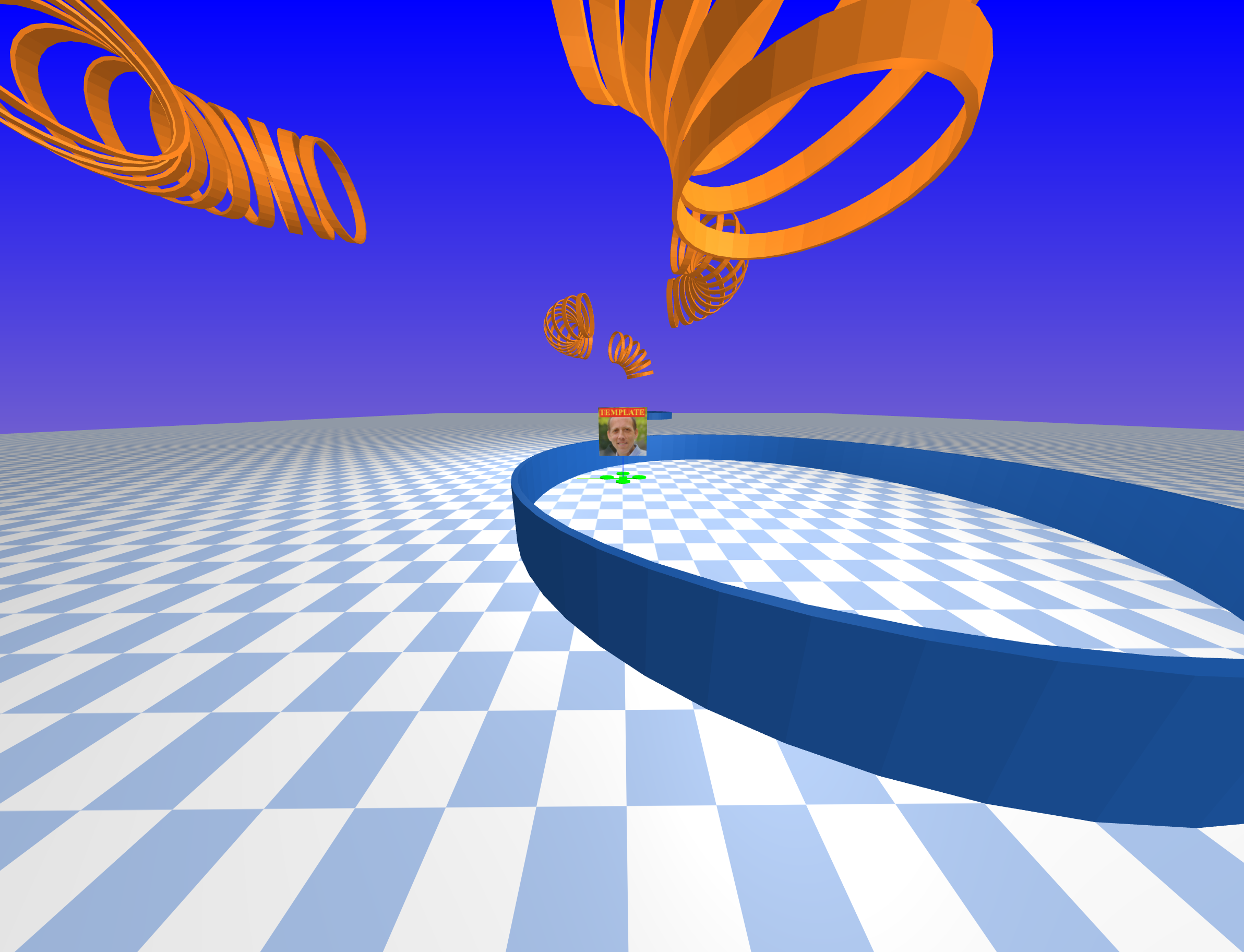
In particular, your drone will be racing with other drones. You will need to take care not to run into these other drones, as collisions may cause drones to crash.
Context
Imagine that, working as a control systems engineer, you have been hired by Tiny Whoop to design a controller for a small-scale drone. In particular, imagine that Tiny Whoop intends to market this drone to amateur pilots for racing (e.g., see their alley cat coffee cup invitational race). Your job is to show that this drone — with a suitable controller — is capable of high-speed, agile flight.
As you work on this project, we encourage you to think about other possible applications of drones such as these. PowderBee from Bluebird Mountain, for example, is intended to find avalanche victims (i.e., people buried under thick snow) quickly so they can be rescued before succumbing to asphyxiation, hypothermia, or other injuries — every second counts in rescue applications, just as for racing drones.
Model
The motion of each drone is governed by ordinary differential equations with the following form:
\[\begin{bmatrix} \dot{p}_x \\ \dot{p}_y \\ \dot{p}_z \\ \dot{\psi} \\ \dot{\theta} \\ \dot{\phi} \\ \dot{v}_x \\ \dot{v}_y \\ \dot{v}_z \\ \dot{w}_x \\ \dot{w}_y \\ \dot{w}_z \end{bmatrix} = f\left(p_x, p_y, p_z, \psi, \theta, \phi, v_x, v_y, v_z, w_x, w_y, w_z, \tau_x, \tau_y, \tau_z, f_z \right)\]In these equations:
- $p_x$ is the $x$ position (m)
- $p_y$ is the $y$ position (m)
- $p_z$ is the $z$ position (m)
- $\psi$ is the yaw angle (rad)
- $\theta$ is the pitch angle (rad)
- $\phi$ is the roll angle (rad)
- $v_x$ is the linear velocity along the body-fixed $x$ axis (m/s)
- $v_y$ is the linear velocity along the body-fixed $y$ axis (m/s)
- $v_z$ is the linear velocity along the body-fixed $z$ axis (m/s)
- $w_x$ is the angular velocity about the body-fixed $x$ axis (rad/s), which points forward
- $w_y$ is the angular velocity about the body-fixed $y$ axis (rad/s), which points left
- $w_z$ is the angular velocity about the body-fixed $z$ axis (rad/s), which points up
- $\tau_x$ is the net torque about the body-fixed $x$ axis ($N\cdot\text{m}$)
- $\tau_y$ is the net torque about the body-fixed $y$ axis ($N\cdot\text{m}$)
- $\tau_z$ is the net torque about the body-fixed $z$ axis ($N\cdot\text{m}$)
- $f_z$ is the net force along the body-fixed $z$ axis ($N$)
A symbolic description of these equations of motion is provided with the project code.
The actuators that produce the net torques $\tau_x, \tau_y, \tau_z$ and net force $f_z$ are the four rotors on the drone, each of which is driven by an electric motor. These rotors can spin in only one direction, and have minimum and maximum speeds. These bounds limit the torques and forces that can actually be produced. These limits are more complicated than simple minimums and maximums. Here are two ways to get a sense for what these limits are:
-
Call the function
(
  tau_x,
  tau_y,
  tau_z,
  f_z,
) = simulator.enforce_motor_limits(
  tau_x_cmd,
  tau_y_cmd,
  tau_z_cmd,
  f_z_cmd,
)
to find the torques and forces that would actually be applied for given torque and force commands. Note that this function cannot be called from within your controller code — it can only be called from elsewhere in your notebook, for the purpose of testing.
-
Use your data from simulation to plot both the torque and force commands as well as the torques and forces that are actually applied. An example is provided in the template notebook.
Ask if you want more details about the mapping from commanded to actual forces and torques.
Sensors provide a noisy measurement of the position in space of two markers (pos_markers), one at the center of the front rotor and one at the center of the rear rotor. This is the sort of measurement that would be provided by a standard commercial motion capture system (e.g., OptiTrak or Vicon). A symbolic description of sensor model is provided with the project code.
In addition to these marker position measurements, your controller is also provided with the following information:
- the position (
pos_ring) of the center of the next ring that the drone needs to pass through - the vector (
dir_ring) normal to this next ring (i.e., pointing through its center) - a flag (
is_last_ring) that indicates if this next ring is the last ring, a.k.a., the “finish” - the position (
pos_others) of all other drones.
The code provided here simulates the motion of this system (DroneDemo) and also derives the dynamic model and sensor model in symbolic form (DeriveEOM).
The goal is to race as fast as possible from the start ring to the goal ring, passing through all the rings in between.
Your tasks
The focus of your analysis this time will be on identifying and diagnosing failures. In this context, a “failure” is anything that causes your drone not to reach the finish ring. There are many reasons why a particular control design might lead to failure. Your job as a control engineer is to uncover and address these sources of failure. At minimum, you should do the following two things for your final control design:
-
Identify as many failures as possible.
-
Diagnose each failure, saying why you think it happened and providing evidence to support your claim.
It is often helpful to put failures into categories — that is, to identify and diagnose types of failures, and to use particular failures as a way to illustrate each type.
Remember that you have practice in doing rigorous data collection, analysis, and visualization (the focus of the third design project). This can help a lot in identifying and diagnosing failures.
You may, of course, be tempted to eliminate failures after you find them, by making some change to your control design. This is exactly the right thing to do, but remember that after you make a change, you’ll have to repeat (completely) your analysis of failure.
Things you need to do
Do the following thing to clarify your goal:
- Define a requirement and a verification, just as you did in the second design project.
Do the following things to produce a control design:
- Linearize the dynamic model and the sensor model.
- Show that the linearized system is both controllable and observable.
- Design a stable controller and a stable observer.
- Add trajectory tracking to enable movement between rings.
- Implement the controller and observer (with trajectory tracking) and test them in simulation.
Do the following things to evaluate your control design:
- Identify and diagnose as many sources of failure as you can find.
- Create at least four figures of aggregate results from at least 100 simulations:
- Show how well your controller is working (e.g., with a histogram of error between actual position and desired position).
- Show how well your observer is working (e.g., with a histogram of error between estimated position and actual position).
- Show how fast your drone completes the race (e.g., with a histogram of completion times). You may also want to show how likely it is that your drone completes the race at all, without failure.
- Show how long it takes your controller to run (e.g., with a histogram of computation times). This will help you avoid being disqualified in the race.
Do the following thing to compete in the race:
- Submit a control design that runs without being disqualified (i.e., it does not raise an exception, it does not print any debug text, and it does not exceed limits on computation time).
There are many ways to go beyond minimum requirements (Can you think of a way to avoid collision with other drones? how do your results change with different amounts of sensor noise? is there a tradeoff between the completion time and the likelihood you complete the race at all?) — come talk to us if you want an extra challenge.
Your deliverables
Draft report with theory (by 11:59pm on Monday, April 17)
Submit a first draft of your report (see below for guidelines) that includes, at minimum, a complete “Introduction” section and a complete “Theory” section. This draft must also include the appendix with your log of all work done so far by each group member.
Upload it to the DP4 Draft 1 group assignment on Canvas.
Draft report with results (by 11:59pm on Monday, April 24)
Submit a second draft of your report (see below for guidelines) that includes, at minimum, a complete “Experimental methods” section and a complete “Results and discussion” section. This draft must also include the appendix with your log of all work done so far by each group member.
Upload it to the DP4 Draft 2 group assignment on Canvas.
Contest entry (by 5:00pm on Tuesday, May 2)
There will be an opportunity to race with your friends in a friendly contest on the last day of class (Wednesday, May 3). The same project code that you are using for the purpose of control design and simulation will be used to run each race in this contest. To enter the race, your team must upload exactly two files to the “DP04-Race-Submissions” Box folder:
netid.py, with a completely self-contained implementation of your control design, in the format specified by 04_drone/students/template.py.netid.png, with an image (keep it professional) that can be used to distinguish your drone from others.
You must, of course, replace netid with your own netid. Please use all lowercase.
Please submit only one pair of files - with the NetID of only one group member - for each group. Your submission will automatically be associated with all members of your group.
All groups are required to entire the race! Your submission will be assessed based on whether or not it satisfies three conditions:
- It must not raise an exception (i.e., throw an error).
- It must not print anything to
stdout(i.e., runprintstatements). - It must not exceed limits on computation time (5 seconds for module load, 1 second for
__init__, 1 second forreset, and5e-3seconds forrun).
Your submission will not be assessed based on whether or not it wins the race.
Final report (by 11:59pm on Tuesday, May 2)
This report will satisfy the following requirements:
- It must be a single PDF document that conforms to the guidelines for Preparation of Papers for AIAA Technical Conferences. In particular, you must use either the Word or LaTeX manuscript template.
- It must have a descriptive title that begins with “DP3” (e.g., “DP3: Control of a spacecraft with reaction wheels and a star tracker”).
- It must have a list of author names and affiliations.
- It must contain the following sections:
- Abstract. Summarize your entire report in one short paragraph.
- Nomenclature. List all symbols used in your report, with units.
- Introduction. Prepare the reader to understand the rest of your report and how it fits within a broader context.
- Theory. Derive a model and do control design.
- Experimental methods. Describe the experiments you performed in simulation in enough detail that they could be understood and repeated by a colleague. This section should also clearly define your requirement and verification.
- Results and discussion. Show the results of your experiments in simulation (e.g., with plots and tables) and discuss the extent to which they validate your control design (including the extent to which they verify your requirement).
- Conclusion. Summarize key conclusions and identify ways that others could improve or build upon your work.
- Acknowledgements. Thank anyone outside your group with whom you discussed this project and clearly describe what you are thanking them for.
- References. Cite any sources, including the work of your colleagues.
- Appendix. See below.
- It must be a maximum of 6 pages (not including the Appendix).
The appendix, which does not count against your page limit, must have a table (with as many rows as necessary) that logs all of the work done by each group member on the project:
| Day | Task | Person or People |
|---|---|---|
The appendix must also have a team reflection in which you summarize your experience working together on the project. What went well? How did you communicate? What might have helped your team be more productive?
Submit your report by uploading it to the DP4 Report group assignment on Canvas.
Final video (by 11:59pm on Tuesday, May 2)
This video will satisfy the following requirements:
- It must be 70 seconds in length.
- The first and last 5 seconds must include text with a descriptive title (the same title as your report), your names, and the following words somewhere in some order:
- AE353: Aerospace Control Systems
- Spring 2023
- Department of Aerospace Engineering
- University of Illinois at Urbana-Champaign
- The middle 60 seconds must clearly communicate your methods and results to potential stakeholders. Who are you designing for? How will your controller help them?
- It must show at least one simulation of your working control system.
- It must stay professional (use good sense, please).
Submit your video by uploading it to the AE353 (Spring 2023) Project Videos channel on Illinois Media Space. Please take care to do the following:
- Use the same descriptive title as your report, appended with your names in parentheses — for example, “DP4: Control of a spacecraft with reaction wheels and a star tracker (Tim Bretl and Jacob Kraft)”.
- Add the tag
dp4(a lower case “dp” followed by the number “4”), so viewers can filter by project number.
You are welcome to resubmit your video at any time before the deadline. To do so, please “Edit” your existing video and then do “Replace Media”. Please do not create a whole new submission.
We realize that 60 seconds is short! Think carefully about what to include (what to show and what to say) and anticipate the need for multiple “takes” and for time spent editing.
Please also submit the URL for your video to the DP4 Video group assignment on Canvas.
Final code (by 11:59pm on Tuesday, May 2)
This code will satisfy the following requirements:
- It must be a single jupyter notebook (with the extension
.ipynb) that, if placed in theprojects/04_dronedirectory and run from start to finish, would reproduce all of the results that you show in your report. - It must not rely on any dependencies other than those associated with the
ae353conda environment. - It must be organized and clearly documented, with a mix of markdown cells and inline comments.
Submit your code by uploading it to the DP4 Code group assignment on Canvas. You will be asked to upload it in two formats — as the original .ipynb (so we can run your code) and as rendered .html (so we can see and comment on your code in Canvas). To get your notebook in .html format, you can do “File” > “Download as” > “HTML (.html)” from the jupyter browser window.
Evaluation
Your project grade will be weighted as follows:
- (10%) Draft report with theory
- (10%) Draft report with results
- (48%) Final report
- (18%) Final video
- (10%) Final code and Race submission
- (4%) Individual reflection
Rubrics will be discussed in class.
Frequently asked questions
May I watch videos that are submitted by other students?
Yes. All videos will be available in the AE353 (Spring 2023) Project Videos channel on Illinois Media Space as soon as they are submitted by your colleagues (see the Video deliverable). You may watch these videos whenever you want, even before you submit your own.
If you are inspired by a video, or if watching a video strongly influences the way you proceed with your own design project, then you must acknowledge and cite this video in your report (and in your own video, if appropriate). Failure to do so would be considered plagiarism.
How do I get started?
The first thing you should do is follow the instructions to download and run course code, verify that you can run the simulation, and mess around a little bit with different actuator commands to get a sense for how the system responds.
After that, if you have read the entire project description and are not sure how to proceed, then take your best guess and ask a question on Campuswire. Improving your ability to get unstuck by asking a good question is an explicit goal of this course.
Design Project #3 (Spacecraft with star tracker)
System
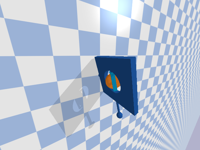
The third project that you will complete this semester is to design, implement, and test a controller that enables a spacecraft to maintain a fixed orientation, as pictured below:
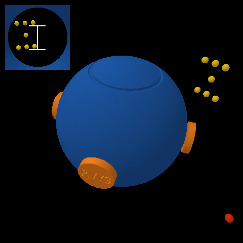
This spacecraft (blue) has four reaction wheels (orange). It is up to you to decide where these reaction wheels are located — the picture shows one among many possibilities. These reaction wheels, like the control moment gyroscope you considered in your first design project, are momentum exchange devices — when a torque is applied to a wheel, an equal and opposite torque is applied to the spacecraft. It is these reaction wheels that will allow your controller to keep the spacecraft pointing in the right direction.
This spacecraft also has a star tracker. This star tracker is a camera that measures the position in an image of each star (yellow) in its field of view. These measured positions, while not perfect, can be compared to where stars should be in order to estimate the orientation and angular velocity of the spacecraft.
Beware! Flying debris (red) may collide with your spacecraft and cause sudden disturbances.
Working as a GNC sub-contractor, you have been asked by a client to design the momentum exchange system (i.e., decide where to put each reaction wheel) as well as to prototype and test a controller that keeps the spacecraft at a fixed orientation despite the flying debris.
Context
Celestial navigation — “using stars, moon, sun, and horizon to calculate position” (or simply the time of day) — dates back thousands of years.
Star trackers — like those from Ball, Terma, or Rocket Lab, for example — take this same concept into space. One key difference is that while celestial navigation on Earth has been used primarily to determine position (i.e., latitude and longitude), star trackers in space are used primarily to determine orientation or “spacecraft attitude.”
The way this works is that star trackers compare the location of stars in an image to a pre-surveyed catalog of stars. In particular, this catalog allows a star tracker to predict the pattern of stars that will be seen in an image as a function of spacecraft orientation. The star tracker searches for the orientation — e.g., for the yaw, pitch, and roll angles — that would make the predicted pattern best match the observed pattern.
Doing this from scratch without a good initial guess is a challenge, and can be slow. Updating an existing estimate of orientation, however, can be done quickly and used for fine guidance. This is what you will do in your own project.
Some of the small satellites that are designed, built, and launched by the Laboratory for Advanced Space Systems at Illinois (LASSI) use star trackers as a critical part of their GNC subsystems. See their description of facilities and research website for more information.
You can read more about star trackers and their use for spacecraft attitude determination — as well as more about reaction wheels and their use for spacecraft attitude control — in Fundamentals of Spacecraft Attitude Determination and Control (Markley and Crassidis, 2014).
Model
The rotational motion of the spacecraft is governed by ordinary differential equations with the following form:
\[\begin{bmatrix} \dot{\psi} \\ \dot{\theta} \\ \dot{\phi} \\ \dot{w_x} \\ \dot{w_y} \\ \dot{w_z} \end{bmatrix} = f\left(\psi, \theta, \phi, w_x, w_y, w_z, \tau_1, \tau_2, \tau_3, \tau_4\right).\]Here are the variables in these equations:
- $\psi$ is the yaw angle (rad)
- $\theta$ is the pitch angle (rad)
- $\phi$ is the roll angle (rad)
- $w_x$ is the angular velocity about the body-fixed $x$ axis (rad/s), which points forward
- $w_y$ is the angular velocity about the body-fixed $y$ axis (rad/s), which points left
- $w_z$ is the angular velocity about the body-fixed $z$ axis (rad/s), which points up
- $\tau_1$ is the torque applied to wheel 1 by a motor on the spacecraft ($N\cdot\text{m}$)
- $\tau_2$ is the torque applied to wheel 2 by a motor on the spacecraft ($N\cdot\text{m}$)
- $\tau_3$ is the torque applied to wheel 3 by a motor on the spacecraft ($N\cdot\text{m}$)
- $\tau_4$ is the torque applied to wheel 4 by a motor on the spacecraft ($N\cdot\text{m}$)
The maximum torque that can be applied by each motor is $\pm 1\;\text{N}\cdot\text{m}$.
A symbolic description of these equations of motion is provided with the project code.
spacecraft.urdf in the urdf directory) that has a model of the spacecraft with your choice of reaction wheel locations.
The sensor is a star tracker. It measures the position (in an image) of each star in its field of view. This measurement has the following form for each star:
\[\begin{bmatrix} y_\text{star} \\ z_\text{star} \end{bmatrix} = g(\psi, \theta, \phi, \alpha, \delta).\]You will already recognize the yaw, pitch, and roll angles in this equation. The other variables are as follows:
- $\alpha$ is the right ascension (rad) of the star
- $\delta$ is the declination (rad) of the star
Again, a symbolic description of this equation is provided with the project code. There are seven stars in total — you can find the parameters $\alpha$ and $\delta$ for each one in the SpacecraftDemo template.
The code provided here simulates the motion of this system (SpacecraftDemo) and also derives both the equations of motion and the sensor model in symbolic form (DeriveEOM).
The goal is to keep the spacecraft close to zero yaw, pitch, and roll for as long as possible despite noisy sensor measurements and space debris.
Why do I say “for as long as possible?” Because the simulator will quit and the spacecraft mission will be declared over when one of two conditions are met:
- Any star leaves the star tracker’s field of view.
- Any reaction wheel has angular velocity that exceeds $\pm 50\;\text{rad}/\text{s}$.
Since you have no way to do momentum dumping (or… do you?), it is inevitable that one of the wheels will eventually spin too fast. Just try to hang on as long as you can.
Your tasks
The focus of your analysis this time will be on data collection. The initial conditions, the sensor measurements, and the disturbances are random. So, for a given control design, your results will vary (perhaps significantly). It is not enough to look at the results of one simulation—you will have to look at the results of many simulations. At minimum, for the final design you consider, you should do the following:
- Collect data from at least 100 simulations that run until failure (i.e., with a very large
max_time). - Plot a histogram of the time until failure across all simulations.
- Plot a histogram of the root-mean-square error (RMSE) in yaw, pitch, and roll angles across all simulations.
Remember that the simulation code provides an option to turn the display off, which can speed up data collection a lot.
Things you need to do
Please do the following things:
- Define a requirement and a verification, just as you did in the second design project.
- Linearize the dynamic model (i.e., the equations of motion) and the sensor model.
- Show that the linearized system is both controllable and observable.
- Design a stable controller and a stable observer.
- Implement both the controller and observer and test them in simulation.
- Follow the instructions you wrote to verify that your requirement is (or is not) satisfied.
- Include at least one figure of aggregate results (e.g., a histogram).
- Include at least one figure that provides evidence the observer is working (e.g., a plot of error in the state estimate as a function of time).
There are many ways to go beyond minimum requirements (how do your results change with different amounts of sensor noise? how do your results change with a different number of arrangement of stars? is there a tradeoff between “time until failure” and “RMSE in yaw, pitch, and roll” or can both measures of performance be improved together? is there a way to use collision with space debris to do momentum dumping?) — come talk to us if you want an extra challenge.
Your deliverables
Draft report with theory (by 11:59pm on Friday, March 24)
Submit a first draft of your report (see below for guidelines) that includes, at minimum, a complete “Introduction” section and a complete “Theory” section. This draft must also include the appendix with your log of all work done so far by each group member.
Upload it to the DP3 Draft 1 group assignment on Canvas.
Draft report with results (by 11:59pm on Friday, March 31)
Submit a second draft of your report (see below for guidelines) that includes, at minimum, a complete “Experimental methods” section and a complete “Results and discussion” section. This draft must also include the appendix with your log of all work done so far by each group member.
Upload it to the DP3 Draft 2 group assignment on Canvas.
Final report (by 11:59pm on Friday, April 7)
This report will satisfy the following requirements:
- It must be a single PDF document that conforms to the guidelines for Preparation of Papers for AIAA Technical Conferences. In particular, you must use either the Word or LaTeX manuscript template.
- It must have a descriptive title that begins with “DP3” (e.g., “DP3: Control of a spacecraft with reaction wheels and a star tracker”).
- It must have a list of author names and affiliations.
- It must contain the following sections:
- Abstract. Summarize your entire report in one short paragraph.
- Nomenclature. List all symbols used in your report, with units.
- Introduction. Prepare the reader to understand the rest of your report and how it fits within a broader context.
- Theory. Derive a model and do control design.
- Experimental methods. Describe the experiments you performed in simulation in enough detail that they could be understood and repeated by a colleague. This section should also clearly define your requirement and verification.
- Results and discussion. Show the results of your experiments in simulation (e.g., with plots and tables) and discuss the extent to which they validate your control design (including the extent to which they verify your requirement).
- Conclusion. Summarize key conclusions and identify ways that others could improve or build upon your work.
- Acknowledgements. Thank anyone outside your group with whom you discussed this project and clearly describe what you are thanking them for.
- References. Cite any sources, including the work of your colleagues.
- Appendix. See below.
- It must be a maximum of 6 pages (not including the Appendix).
The appendix, which does not count against your page limit, must have a table (with as many rows as necessary) that logs all of the work done by each group member on the project:
| Day | Task | Person or People |
|---|---|---|
The appendix must also have a team reflection in which you summarize your experience working together on the project. What went well? How did you communicate? What might have helped your team be more productive?
Submit your report by uploading it to the DP3 Report group assignment on Canvas.
Final video (by 11:59pm on Friday, April 7)
This video will satisfy the following requirements:
- It must be 70 seconds in length.
- The first and last 5 seconds must include text with a descriptive title (the same title as your report), your names, and the following words somewhere in some order:
- AE353: Aerospace Control Systems
- Spring 2023
- Department of Aerospace Engineering
- University of Illinois at Urbana-Champaign
- The middle 60 seconds must clearly communicate your methods and results to potential stakeholders. Who are you designing for? How will your controller help them?
- It must stay professional (use good sense, please).
Submit your video by uploading it to the AE353 (Spring 2023) Project Videos channel on Illinois Media Space. Please take care to do the following:
- Use the same descriptive title as your report, appended with your names in parentheses — for example, “DP3: Control of a spacecraft with reaction wheels and a star tracker (Tim Bretl and Jacob Kraft)”.
- Add the tag
dp3(a lower case “dp” followed by the number “3”), so viewers can filter by project number.
You are welcome to resubmit your video at any time before the deadline. To do so, please “Edit” your existing video and then do “Replace Media”. Please do not create a whole new submission.
We realize that 60 seconds is short! Think carefully about what to include (what to show and what to say) and anticipate the need for multiple “takes” and for time spent editing.
Please also submit the URL for your video to the DP3 Video group assignment on Canvas.
Final code (by 11:59pm on Friday, April 7)
This code will satisfy the following requirements:
- It must be a single jupyter notebook (with the extension
.ipynb) that, if placed in theprojects/03_spacecraftdirectory and run from start to finish, would reproduce all of the results that you show in your report. - It must not rely on any dependencies other than those associated with the
ae353conda environment. - It must be organized and clearly documented, with a mix of markdown cells and inline comments.
Submit your code by uploading it to the DP3 Code group assignment on Canvas. You will be asked to upload it in two formats — as the original .ipynb (so we can run your code) and as rendered .html (so we can see and comment on your code in Canvas). To get your notebook in .html format, you can do “File” > “Download as” > “HTML (.html)” from the jupyter browser window.
Individual reflection (by 11:59pm on Monday, April 10)
Complete the DP3 Reflection assignment on Canvas sometime between 3:00pm on Friday, April 7 and 11:59pm on Monday, April 10. This assignment, which should take no more than 10 or 15 minutes, will give you a chance to reflect on your experiences during this project and to identify things you may want to change for the next project.
Evaluation
Your project grade will be weighted as follows:
- (10%) Draft report with theory
- (10%) Draft report with results
- (48%) Final report
- (18%) Final video
- (10%) Final code
- (4%) Individual reflection
Rubrics will be discussed in class.
Frequently asked questions
May I watch videos that are submitted by other students?
Yes. All videos will be available in the AE353 (Spring 2023) Project Videos channel on Illinois Media Space as soon as they are submitted by your colleagues (see the Video deliverable). You may watch these videos whenever you want, even before you submit your own.
If you are inspired by a video, or if watching a video strongly influences the way you proceed with your own design project, then you must acknowledge and cite this video in your report (and in your own video, if appropriate). Failure to do so would be considered plagiarism.
How do I get started?
The first thing you should do is follow the instructions to download and run course code, choose a placement of reaction wheels using the DeriveEOM notebook, verify that you can run a simulation using the SpacecraftDemo notebook, and mess around with different actuator commands (e.g., constant wheel torques) to get a sense for how the system response.
After that, if you have read the entire project description and are not sure how to proceed, then take your best guess and ask a question on Campuswire. Improving your ability to get unstuck by asking a good question is an explicit goal of this course.
Design Project #2 (Differential-drive robot in artificial gravity)
System
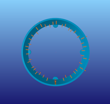
The second project that you will complete this semester is to design, implement, and test a controller that enables a client — who is not an engineer — to steer a differential-drive robot quickly and safely around obstacles as it moves along the inside of a rotating space station under artificial gravity while avoiding hazards, as pictured below:
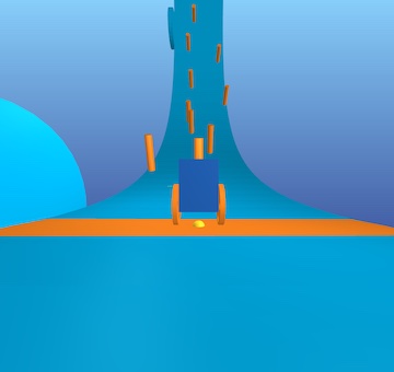
This robot consists of a chassis (dark blue), a left wheel (orange), and a right wheel (also orange). It is called “differential-drive” because two separate motors allow a different torque to be applied to the left wheel and the right wheel:
- If both wheels are rotating forward at the same rate, the robot moves straight.
- If the left wheel is rotating forward faster than the right wheel, the robot turns right.
- If the right wheel is rotating forward faster than the left wheel, the robot turns left.
The client will be given an interface that allows them to specify where on the station ring — farther to the left or farther to the right — they would like the robot to go (this desired position is indicated by a yellow sphere). The job of your controller is to get the robot there while keeping it balanced upright.
Context
A differential-drive transmission is a common design choice for mobile robots. For example, NASA used it in a prototype of Robonaut. You can read more about the reasons why in the textbook Introduction to Autonomous Mobile Robots, Second Edition (Siegward, Nourbakhsh, and Scaramuzza, 2011), also available online (for free from the library at Illinois and at other academic institutions). The two-wheeled, differential-drive design has, of course, also been popularized by Segway.
Artificial gravity is one way to keep a mobile robot anchored to a space station. In particular, if the space station is rotation with angular velocity $\omega_\text{station}$ and if the radius of the station — the distance from the center of rotation to its inner surface — is $r_\text{station}$, then the robot will “feel” as if it were being pulled outward by gravity with acceleration equal to the centripetal accleration
\[g = r_\text{station}\omega_\text{station}^2.\]Artificial gravity is also one way to mitigate the health impacts of microgravity on human astronauts. For example, astronauts lose more than 1% of mineral density in weight-bearing bones for each month they are in zero gravity (see The Human Body in Space for more information).
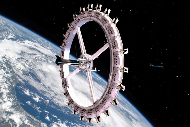
Many assessments of artificial gravity in space missions have been performed by NASA and others, resulting in concepts like Nautilus-X or the Voyager Space Station, a “space hotel” pictured below that may begin construction as early as 2026:
Model
If we assume (incorrectly) that the inside of the space station is flat and not curved upward, then the motion of the system is governed by ordinary differential equations with the following form (see Studies of Systems with Nonholonomic Constraints: the Segway and the Chaplygin Sleigh (Tuttle, 2014) for a derivation):
\[\begin{bmatrix} \dot{e}_\text{lateral} \\ \dot{e}_\text{heading} \\ \dot{v} \\ \dot{w} \\ \ddot{\theta} \end{bmatrix} = f(e_\text{lateral}, e_\text{heading}, v, w, \theta, \dot{\theta}, \tau_R, \tau_L)\]The details of the function $f$ get a little complicated:
\[\begin{bmatrix}v \sin{\left(e_\text{heading} \right)}\\w\\- \frac{2400 \tau_{L} + 2400 \tau_{R} + 2808 \left(\dot{\theta}^{2} + w^{2}\right) \sin{\left(\theta \right)} + 65 \left(50 \tau_{L} + 50 \tau_{R} - 39 w^{2} \sin{\left(2 \theta \right)} - 900 \sin{\left(\theta \right)}\right) \cos{\left(\theta \right)}}{11700 \cos^{2}{\left(\theta \right)} - 12168}\\\frac{32 \left(- 875 \tau_{L} + 875 \tau_{R} - 1443 \dot{\theta} w \sin{\left(2 \theta \right)} - 2925 v w \sin{\left(\theta \right)}\right)}{13 \left(3120 \sin^{2}{\left(\theta \right)} + 2051\right)}\\\frac{5 \left(8450 \tau_{L} + 8450 \tau_{R} - 6591 w^{2} \sin{\left(2 \theta \right)} + 60 \left(100 \tau_{L} + 100 \tau_{R} + 117 \left(\dot{\theta}^{2} + w^{2}\right) \sin{\left(\theta \right)}\right) \cos{\left(\theta \right)} - 152100 \sin{\left(\theta \right)}\right)}{1404 \left(25 \cos^{2}{\left(\theta \right)} - 26\right)}\end{bmatrix}\]So, you are encouraged to use the symbolic description of these equations of motion that is provided with the project code — there is no need to transcribe them yourself.
In these equations:
- $e_\text{lateral}$ is the lateral error (m), or the distance from the center of the robot (more precisely, from the wheel center, or the point halfway between its two wheels) to a line that passes through the yellow sphere around the station ring — if this quantity is positive, then the robot is too far to the left; if this quantity is negative, then the robot is too far to the right
- $e_\text{heading}$ is the heading error (rad), or the difference between the orientation of the robot and the direction of the station ring — if this quantity is positive, then the robot is pointing to far to the left; if this quantity is negative, then the robot is pointing too far to the right
- $v$ is the forward speed (m/s) — positive means the robot is moving forward
- $w$ is the turning rate (rad/s) — positive means the robot is turning left
- $\theta$ is the pitch angle (rad) — positive means the chassis is pitching forward
- $\dot{\theta}$ is the pitch rate (rad/s)
- $\tau_R$ is the right wheel torque ($N\cdot\text{m}$) applied by the chassis to the right wheel — positive torque will cause this wheel to rotate forward
- $\tau_L$ is the left wheel torque ($N\cdot\text{m}$) applied by the chassis to the left wheel — positive torque will cause this wheel to rotate forward
Sensors provide measurements of all these variables (although these sensors do not provide any information about the station ring — the extent to which it is curving upward or the location of obstacles, for example). Actuators allow you to choose what torques will be applied, up to a maximum of $\pm 1\;\text{N}\cdot\text{m}$.
The code provided here simulates the motion of this system (SegbotDemo) and also derives the equations of motion in symbolic form (DeriveEOM).
The goal is to design a controller that enables a client who is not an engineer to steer the robot as fast as possible around the ring of the space station without causing it to fall off the edge or to hit any obstacles.
Your tasks
In this project, we would like you to be more specific about what you mean by “success” and to provide quantitative evidence supporting the claim that you have (or have not) succeeded. People often think about this in terms of requirements and verifications.
What is a requirement?
A requirement is a property that the system you are designing must have in order to solve your problem (i.e., a thing that needs to get done). A good requirement is quantifiable—it involves a number that must be within a certain range in order to solve your design problem. A good requirement is also both relevant (it must be satisfied—it is not optional) and detailed (it can be read and understood by anyone). Here is an example of a requirement that says what needs to get done but that most engineers would consider unacceptable:
The robot shall move along the ring.
This requirement is not detailed. One way to improve it would be to say what it means to move along the ring:
The wheel center shall remain close to the centerline of the ring.
This requirement is not quantifiable. One way to improve it would be to say how close:
The wheel center shall remain within $\pm 0.1~\text{meters}$ of the ring centerline.
Most engineers would argue that this requirement still needs improvement. How long must the wheel center remain close to the centerline of the ring? Is there an upper bound on the time it must take for the wheel center to get close to the centerline of the ring, assuming it starts somewhere else? Must this requirement be satisfied only if the station is spinning at its nominal rate, or must it be satisfied for any spin rate within certain bounds? Must this requirement be satisfied no matter what the initial conditions are? Or, are there particular operating conditions within which the requirement applies? How fast must the robot be moving along the ring? Must the robot remain upright and moving at all in order to satisfy this requirement, or can it fall over and remain still so long as its wheel center is near the centerline of the ring when it falls? These are examples of reasonable questions that might be asked by an engineer reviewing the requirement. Your task is to define one requirement—that is quantifiable, relevant, and detailed—that makes clear what the system you are designing must do in order for your goal to be achieved.
Below follows a brief, and incomplete, list of guidlines followed by most engineers while writing requirements:
-
Shall formatting: Requirements shall be in “shall” format. A requirement should use the language: “ITEM A shall TASK A”. This language minimizes ambiguity.
-
Compound requirements: Requirements should not have and conjunctions or transitions in them. For example, try to avoid “and”, “but”, “or”, “further”, “also:, etc. If you use these words, often you are defining two separate requirements.
-
Ambiguous requirements: Requirements shall be simple sentences that minimize ambiguity. You should not include time constraints without stating the point from which timing begins. You should not include maximum limits without defining the equilibrium conditions. You should not use ambiguous language that you do not FIRST (before the requirements and verifications) define.
-
Requirements without initial conditions: It is insufficient to say “The absolute value of MEASURE A shall not exceed CONSTRAINT A.” when you are talking about a measure that changes with time, depends on initial conditions, and varies with user inputs. For example, what if MEASURE A is the pitch of an aircraft and CONSTRAINT A is 5 degrees. The absolute value of the pitch angle shall not exceed 5 degrees. To satisfy this requirement, you must design a system that is not capable of producing pitch angles that exceed 5 degrees. Whereas this may be what an engineer wants, often it is not. Instead, consider the requirement “Given an initial condition of CONDITION A and user input of INPUT A, the absolute value of MEASURE A shall not exceed CONSTRAINT A.”
-
Unverifiable requirements: Requirements must be verifiable. This means that you must be able to prove that they are exactly met or not. For example, the requirement “The MEASURE shall be less than CONSTRAINT A after CONSTRAINT B seconds from initialization for all initial conditions between CONDITION A and CONDITION B.“ is not verifiable in simulation. This is because there are uncountably infinite initial conditions between CONDITION A and CONDITION B. To verify this requirement in simulation, one would have to run infinite simulations. Consider this instead, “The MEASURE shall be less than CONSTRAINT A after CONSTRAINT B seconds from initialization for initial condition CONDITION A.”, “The MEASURE shall be less than CONSTRAINT A after CONSTRAINT B seconds from initialization for initial condition CONDITION B.”,”, “The MEASURE shall be less than CONSTRAINT A after CONSTRAINT B seconds from initialization for initial condition CONDITION C.”,”. This set of requirements is verifiable in simulation because there are only a finite number of initial conditions that must be simulated.
-
Plus and minus: Engineers are often tempted to use the ± symbol in requirements and verifications. Often, this is a mistake. The requirement “MEASURE A shall remain within the limits ± CONTRAINT A” can be ambiguous. Are you defining a connected range or a disconnected range? Language such as “The absolute magnitude of MEASURE A shall not exceed CONSTRAINT A” is less ambiguous. Here it is clear that you are using a connected range.
-
Requirements that constraint design: Requirements should never constrain the design of a system. For example, if a system needs to allow astronauts to enter it and to exit it in space “The system shall include an airlock” is an insufficient requirement. This is because this requirement enforces that the system uses an airlock. Instead, consider “The system shall support egress of humans in space”. “The system shall support ingress of humans in space”. These requirements do not constrain the design of the system at all.
-
Requirements of a requirement: A requirement of a requirement should not be used. For example, you should not say “Our requirements must be sufficient to enforce TASK A.”. Instead, list goals and accompanying requirements. For example, “The goal of the project is to ITEM A. Therefore, the system shall TASK A subject to CONSTRAINTS A”.
What is a verification?
A verification is a test that you will perform to make sure that the system you are designing meets a given requirement. A good verification is based on a measurement—it checks that a quantity is in the range specified by the requirement. A good verification also has a set of instructions for how to make the measurement (an experimental protocol) and for how to interpret the results (methods of data analysis and visualization that provide evidence the requirement has been met). Consider the requirement given above (which, as we have said, still needs improvement):
The wheel center shall remain within $\pm 0.1~\text{meters}$ of the ring centerline.
Here is a verification of this requirement that most engineers would consider unacceptable:
The system will be tested in simulation.
This verification is not based on a measurement. Here is a better version that is based on a measurement:
The error between the wheel center and the ring centerline will be found in simulation.
This verification does not include a set of instructions for how to make the measurement or for how to interpret the results. Here is a better version that does include a set of instructions:
PyBullet will be be used to simulate the robot. The data generated by this simulation will be imported into a Jupyter Notebook for analysis with Python. The lateral error — the perpendicular distance between the wheel center and the ring centerline — will be found at each time step. The maximum absolute value of lateral error over all time steps will be reported. If this maximum value is less than $0.1~\text{meters}$, the requirement is met.
Most engineers would argue that this verification still needs improvement. For example, does the simulation generate the same results every time, or is there variation? Just as you saw on your first design project, it seems reasonable to suspect that different initial conditions will produce different results. A reasonable engineer, then, would question whether or not the results of only one simulation would really show that the requirement is met. Many verifications also provide more than just a single number as evidence—for example, they might produce a figure (e.g., a plot of error as a function of time) or some other type of visualization. Your task is to define one verification for your requirement that has a measurement and a set of instructions for how to make the measurement and how to interpret the results.
Below follows a brief, and incomplete, list of guidelines followed by most engineers while writing verifications:
-
Types of verifications: There are four fundamental ways to verify a requirement. This is by inspection, demonstration, test, and analysis. In this order, each verification method increases in rigor.
-
Verification by inspection: Verification by inspection relies on visual, auditory, olfactory, tactile, taste observations from humans. Suppose the requirement is: “The system shall be red”. An example of verification by inspection is as follows: “REQUIREMENT A is verified by inspection. A randomized group of 15 volunteers will be asked to observer the system. They will be asked ‘What color is this system’, and their responses will be recorded. REQUIREMENT A is verified if and only if the majority of the volunteers’ responses include the keyword ‘red’”.
-
Verification by demonstration: Verification by demonstration is the manipulation of the system as intended in use to verify the results satisfy the parent requirements. Suppose the requirement is: “The system shall move box 32-DCA from location 16-B and place it in location 17-B”. An example of verification by demonstration is as follows: “REQUIREMENT A is verified by demonstration. Box 32-DCA is placed in location 16-B. The system is placed 0.5 meters away radially from box 32-DCA on a shared level surface. The system is initiated. REQUIREMENT A is verified if and only if box 32-DCA is in location 17-B upon system termination.”
-
Verification by test (often called verification by simulation): Verification by test is the process by which the system is subjected to a finite number of tests. A test is defined as a predetermined time series of initial conditions, user inputs, system conditions, etc. Suppose the requirement is: “The absolute magnitude of the system’s speed shall not exceed 0.5m/s”. An example of verification by test is as follows: “REQUIREMENT A is verified by test. The system is initialized in CONDITION A. Virtual user inputs are scheduled as INPUTS A. The system is engaged. After 10 seconds, the system is disengaged. The speed of the system is recorded via doppler radar every 0.25 seconds from engage to disengage. The maximum speed recorded by the doppler radar is recorded as MAXIMUM A. The system is initialized in CONDITION B. Virtual user inputs are scheduled as INPUTS B. The system is engaged. After 10 seconds, the system is disengaged. The speed of the system is recorded via doppler radar every 0.25 seconds from engage to disengage. The maximum speed recorded by the doppler radar is recorded as MAXIMUM B. REQUIREMENT A is verified if and only if MAXIMUM A is less than or equal to 0.5m/s and MAXIMUM B is less than or equal to 0.5m/s.”
-
Verification by analysis: Verification by analysis is the process by which a system is analyzed via models and calculations. This varies from verification by test because no specific experiments are conducted. Suppose the requirement is: “The absolute magnitude of the system’s speed shall not exceed 0.5m/s”. An example of verification by analysis is as follows: “REQUIREMENT A is verified by analysis. The equations of motion of the system are derived via Lagrangian mechanics. The time solution of the system’s speed is solved via the method of undetermined coefficients. The maximum of the time solution of the system’s speed as a function of the initial conditions and user inputs is determined via the Karush-Kuhn-Tucker theorem. REQUIREMENT A is verified if and only if the global maximum of the time solution of the system’s speed is less than or equal to 0.5m/s for all admissible initial conditions and user inputs.”
-
Required information in verifications: Just like the “Experimental Methods” section of a journal style paper, verifications should describe the steps that will be performed in enough detail that they could be understood and repeated exactly by a colleague with no exposure to this class or this design project. For example, it is insufficient to say “REQUIREMENT A will be verified via simulation”
-
Negative form of verification: Verifications must not be written in negative form, i.e., “… if MEASURE A exceeds CONSTRAINT B, then the requirement is not verified.”. In general, verifications are written in the positive form, i.e., “… if the MEASURE A is less than the CONSTRAINT B, then the requirement is verified.”
-
Errors regarding data collection in verifications: When a verification uses data collection, there must be no ambiguity surround these data. You must explicitly state which data are collected, when the collection starts, at which frequency the data is collected, which tool is used to generate the data, and exactly how the data is analyzed. It is insufficient to say “REQUIREMENT A is verified by running a simulation and collecting the data that it gives. If the MEASURE A does not exceed CONSTRAINT A, the requirement is verified.” Instead, consider, “REQUIREMENT A is verified by running an instance of the PyBullet simulation provided at SOURCE A subject to INITIAL CONDITION A. MEASURE A, MEASURE B, and MEASURE C are output from the simulation at a frequency of FREQUENCY A. These data are gathered for a duration of LEGNTH A seconds. When LENGTH A seconds have elapsed, these data are analyzed by METHOD A. REQUIREMENT A is verified if, and only if, METHOD A of MEASURE A, MEASURE B, and MEASURE C proves that MEASURE A does not exceed CONSTRAINT A.”
-
Ambiguous data description in verification: Engineers must avoid ambiguity when discussing data analysis. This is especially true with respect to verifications. If data is generated that are used to verify a requirement, the analysis proving the verification of the requirement must be understood by all peers, even those with no exposure to the project. For example, it is insufficient to say, “REQUIREMENT A is verified with the MEASURE A has VALUE A at the final time step.” What does final time step mean? What are time steps? Instead, consider “A rollout is defined as a simulation with initial conditions of CONDITIONS A and a duration of DURATION A. REQUIREMENT A is verified if and only if MEASURE A has VALUE A at DURATION A of a rollout.”
-
Visual verification of graphs: Visual verification of graphs is an insufficient method of verification. If numerical data is generated, numerical data must be used in verification.
Ambiguous language in requirements and verifications
Many words and phrases are ambiguous and either require strict definitions or should not be used. They can have more than one meaning depending on the reader and background. Be sure that all language in requirements and verifications is not ambiguous at all. Imagine you have no background knowledge in either this project or engineering. Your requirements and verifications should still be easily understandable. Below follows a brief, and incomplete, list of ambiguous words and phrases avoided by most engineers while writing requirements and verifications:
- converge
- final
- end
- means
- good
- complete
- sufficient
- varying
- error
- fulfilled
- original
- upper
- lower
- within
- be able to
- be capable of
What requirement and verification would be most relevant?
Remember that your goal is to enable a non-expert to steer the robot safely around the station while avoiding obstacles. Think about requirements and verifications in terms of your client’s needs. What must be satisfied by your control system to enable safe steering?
Things you need to do
Please do the following things:
- Define a requirement and a verification.
- Linearize the equations of motion.
- Show that the linearized system is controllable.
- Design a stable controller.
- Implement this controller and test it in simulation.
- Follow the instructions you wrote to verify that your requirement is (or is not) satisfied.
As always, remember that your controller is not expected to “work” in all cases and that you should try hard to establish limits of performance (i.e., to break your controller). At minimum, you should rigorously vary the initial conditions, as you did in your first design project.
Please also test the ability of at least one real person to steer the robot — with your controller — safely around the station ring. It would be best if this person were a real “non-expert” — someone not in your group, not in this class, and maybe outside the college of engineering!
There are many ways to go beyond minimum requirements (how does the spin rate impact the performance of your controller? how fast is it possible to get the robot to move around the ring without it falling off, falling down, or hitting anything? how does performance vary with the choice of speed at which the robot tries to move?) — come talk to us if you want an extra challenge.
Your deliverables
Note that final deliverables are due the day before spring break - plan accordingly!
Draft report with theory (by 11:59pm on Friday, February 24)
Submit a first draft of your report (see below for guidelines) that includes, at minimum, a complete “Theory” section. This draft must also include the appendix with your log of all work done so far by each group member.
Upload it to the DP2 Draft 1 group assignment on Canvas.
Draft report with results (by 11:59pm on Friday, March 3)
Submit a second draft of your report (see below for guidelines) that includes, at minimum, a complete “Experimental methods” section and a complete “Results and discussion” section. This draft must also include the appendix with your log of all work done so far by each group member.
Upload it to the DP2 Draft 2 group assignment on Canvas.
Final report (by 11:59pm on Friday, March 10)
This report will satisfy the following requirements:
- It must be a single PDF document that conforms to the guidelines for Preparation of Papers for AIAA Technical Conferences. In particular, you must use either the Word or LaTeX manuscript template.
- It must have a descriptive title that begins with “DP2” (e.g., “DP2: Control of a differential-drive robot in artificial gravity”).
- It must have a list of author names and affiliations.
- It must contain the following sections:
- Abstract. Summarize your entire report in one short paragraph.
- Nomenclature. List all symbols used in your report, with units.
- Introduction. Prepare the reader to understand the rest of your report and how it fits within a broader context.
- Theory. Derive a model and do control design.
- Experimental methods. Describe the experiments you performed in simulation in enough detail that they could be understood and repeated by a colleague. At minimum, this section should clearly define your requirement and verification.
- Results and discussion. Show the results of your experiments in simulation (e.g., with plots and tables) and discuss the extent to which they validate your control design - in particular, the extent to which they verify your requirement. As always, remember to focus on establishing limits of performance.
- Conclusion. Summarize key conclusions and identify ways that others could improve or build upon your work.
- Acknowledgements. Thank anyone outside your group with whom you discussed this project and clearly describe what you are thanking them for.
- References. Cite any sources, including the work of your colleagues.
- Appendix. See below.
- It must be a maximum of 6 pages.
The appendix, which does not count against your page limit, must have a table (with as many rows as necessary) that logs all of the work done by each group member on the project:
| Day | Task | Person or People |
|---|---|---|
The appendix must also have a team reflection in which you summarize your experience working together on the project. What went well? How did you communicate? What might have helped your team be more productive?
Submit your report by uploading it to the DP2 Report group assignment on Canvas.
Final video (by 11:59pm on Friday, March 10)
This video will satisfy the following requirements:
- It must be 70 seconds in length.
- The first and last 5 seconds must include text with a descriptive title (the same title as your report), your names, and the following words somewhere in some order:
- AE353: Aerospace Control Systems
- Spring 2023
- Department of Aerospace Engineering
- University of Illinois at Urbana-Champaign
- The middle 60 seconds must clearly communicate your methods and results to potential stakeholders. Who are you designing for? How will your controller help them?
- It must show at least one example of a non-expert steering your robot around the station ring.
- It must stay professional (use good sense, please).
Submit your video by uploading it to the AE353 (Spring 2023) Project Videos channel on Illinois Media Space. Please take care to do the following:
- Use the same descriptive title as your report, appended with your names in parentheses — for example, “DP2: Control of a differential-drive robot in artificial gravity (Tim Bretl and Jacob Kraft)”.
- Add the tag
dp2(a lower case “dp” followed by the number “2”), so viewers can filter by project number.
You are welcome to resubmit your video at any time before the deadline. To do so, please “Edit” your existing video and then do “Replace Media”. Please do not create a whole new submission.
We realize that 60 seconds is short! Think carefully about what to include (what to show and what to say) and anticipate the need for multiple “takes” and for time spent editing.
Please also submit the URL for your video to the DP2 Video group assignment on Canvas.
Final code (by 11:59pm on Friday, March 10)
This code will satisfy the following requirements:
- It must be a single jupyter notebook (with the extension
.ipynb) that, if placed in theprojects/02_segbotdirectory and run from start to finish, would reproduce all of the results that you show in your report. - It must not rely on any dependencies other than those associated with the
ae353conda environment. - It must be organized and clearly documented, with a mix of markdown cells and inline comments.
Submit your code by uploading it to the DP2 Code group assignment on Canvas. You will be asked to upload it in two formats — as the original .ipynb (so we can run your code) and as rendered .html (so we can see and comment on your code in Canvas). To get your notebook in .html format, you can do “File” > “Download as” > “HTML (.html)” from the jupyter browser window.
Individual reflection (by 11:59pm on Monday, March 20)
Complete the DP2 Reflection assignment on Canvas sometime between 3:00pm on Friday, March 10 and 11:59pm on Monday, March 20. This assignment, which should take no more than 10 or 15 minutes, will give you a chance to reflect on your experiences during this project and to identify things you may want to change for the next project.
Evaluation
Your project grade will be weighted as follows:
- (10%) Draft report with theory
- (10%) Draft report with results
- (48%) Final report
- (18%) Final video
- (10%) Final code
- (4%) Individual reflection
Rubrics will be discussed in class.
Frequently asked questions
May I watch videos that are submitted by other students?
Yes. All videos will be available in the AE353 (Spring 2023) Project Videos channel on Illinois Media Space as soon as they are submitted by your colleagues (see the Video deliverable). You may watch these videos whenever you want, even before you submit your own.
If you are inspired by a video, or if watching a video strongly influences the way you proceed with your own design project, then you must acknowledge and cite this video in your report (and in your own video, if appropriate). Failure to do so would be considered plagiarism.
How do I get started?
The first thing you should do is follow the instructions to download and run course code, verify that you can run the simulation, and mess around a little bit with different actuator commands (e.g., constant wheel torques) to get a sense for how the system responds.
After that, if you have read the entire project description and are not sure how to proceed, then take your best guess and ask a question on Campuswire. Improving your ability to get unstuck by asking a good question is an explicit goal of this course.
Design Project #1 (CMG)
System
The first project that you will complete this semester is to design, implement, and test a controller that uses a single-gimbal control moment gyroscope (CMG) to reorient a platform in a gravitational field, as pictured below:
This system has three parts:
- A platform (dark blue) that can rotate freely about its base. Think of this as a spacecraft that is confined to rotate about its pitch axis, as if it were being tested on the ground.
- A gimbal (light blue) that can be driven by a motor to rotate about a perpendicular axis with respect to the platform.
- A rotor (orange) that can be driven by a motor to spin about yet another perpendicular axis with respect to the gimbal.
If the rotor is spun at a high rate, then an “input torque” applied to the gimbal will, through conservation of angular momentum, result in an “output torque” applied to the platform. This output torque can be used, in particular, to change the orientation of the platform.
Context
Reaction wheels and control-moment gyroscopes (CMGs) are two different non-propulsive actuators (i.e., actuators that do not consume fuel) that are commonly used to control the attitude of spacecraft.
A reaction wheel spins at a variable rate about an axis that is fixed with respect to the spacecraft. If the spacecraft applies a torque to this wheel with a motor (either speeding it up or slowing it down), then an equal and opposite torque is applied to the spacecraft.
A single-gimbal CMG also has a spinning wheel, but with two key differences: (1) the wheel spins at a constant rate instead of at a variable rate, and (2) the wheel is held by a gimbal that allows the axis of spin to be tilted with respect to the spaceraft instead of staying fixed.
In particular, if the wheel in a single-gimbal CMG — often called a rotor — is spun at a high rate, then an “input torque” applied to the gimbal will, through conservation of angular momentum, result in an “output torque” applied to the platform about an axis perpendicular both to the gimbal axis and the rotor axis.
One advantage of using a single-gimbal CMG over a reaction wheel is that this output torque can be much higher than the input torque — a so-called “torque amplification” effect. That is to say, CMGs have the ability to generate large torques with relatively low power consumption. This makes them well-suited for long-duration space missions — including geosynchronous satellites and interplanetary probes — where power and weight constraints are significant considerations. This also means that CMGs can, in general, produce much larger torques than reaction wheels, which can be useful for attitude control of very large spacecraft. The International Space Station (ISS) is one example of a large spacecraft whose attitude is controlled by CMGs — here is an image of a CMG being installed on ISS by an STS-118 crew member:
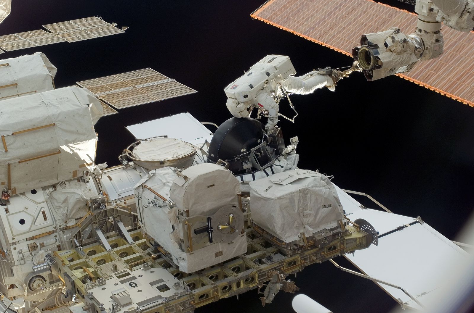
ISS uses four double-gimbal CMGs rather than the one single-gimbal CMG you will be considering in this project, although the principles of operation are similar. These CMGs have a life expectency of about 10 years, contain a rotor that spins at 691 rad/s (6600 rpm), and can produce an output torque of 258 N-m (190 ft-lbf). The orientation of ISS can be fine-tuned to point exactly at a target By controlling the tilt of each CMG.
There are disadvantages to using CMGs instead of reaction wheels, of course. One disadvantage, for example, is that the dynamics of a CMG are more complicated than those of a reaction wheel and require a more sophisticated controller.
This first design project will familiarize you with the operational concepts and physics behind the use of CMGs on modern spacecraft, and in particular will give you a sense of what it takes to control them.
You can read more about CMGs and their use for spacecraft attitude control in Fundamentals of Spacecraft Attitude Determination and Control (Markley and Crassidis, 2014).
Model
The motion of the system is governed by the following ordinary differential equations:
\[\begin{aligned} \ddot{q}_1 &= \dfrac{a_1 \sin(2q_2) \dot{q}_1\dot{q}_2 + a_2\cos(q_2)\dot{q}_2v_\text{rotor} + a_3\sin(q_1)}{a_4 + a_5\cos^2(q_2)} \\[1em] \ddot{q}_2 &= a_6 \sin(2q_2)\dot{q}_1^2 + a_7\cos(q_2)\dot{q}_1v_\text{rotor} + a_8\tau \end{aligned}\]In these equations, the following variables are functions of time:
- $q_1$ and $\dot{q}_1$ are the angle (rad) and angular velocity (rad/s) of the platform
- $q_2$ and $\dot{q}_2$ are the angle (rad) and angular velocity (rad/s) of the gimbal
- $\tau$ is the torque (N$\cdot$m) applied by the platform to the gimbal
The following variable is also a function of time, although you may assume that it is constant (a PID controller was designed and implemented for you that tries to ensure this is true):
- $v_\text{rotor} = 500$ is the angular velocity (rad/s) of the rotor
All other parameters are constant:
\[\begin{aligned} a_1 &= - J_{3y} + 2 J_{3z} \\ a_2 &= 2 J_{3y} \\ a_3 &= - 2 g m r \\ a_4 &= 2 J_{1z} + 2 J_{2z} + 2 m r^{2} \\ a_5 &= 2 J_{3z} \\ a_6 &= \frac{J_{3y} - J_{3z}}{2 \left(J_{2x} + J_{3x}\right)} \\ a_7 &= - \frac{J_{3y}}{J_{2x} + J_{3x}} \\ a_8 &= \frac{1}{J_{2x} + J_{3x}} \end{aligned}\]These parameters are defined in terms of the following quantities:
- $J_{1z} = 0.5\;\text{kg}\cdot\text{m}^2$, one principal moment of inertia of the platform
- $J_{2x} = J_{2z} = 0.001\;\text{kg}\cdot\text{m}^2$, two principal moments of inertia of the gimbal
- $J_{3x} = J_{3y} = J_{3z} = 0.01\;\text{kg}\cdot\text{m}^2$, principal moments of inertia of the rotor
- $m = 1.0\;\text{kg}$, the mass of the boom
- $r = 2.0\;\text{m}$, the length of the boom
- $g = 9.81\;\text{m}/\text{s}^2$, the acceleration of gravity
Sensors provide measurements of the angle and angular velocity of both the platform and the gimbal. Actuators allow you to choose what torque will be applied by the platform to the gimbal, up to a maximum of $\pm 1\;\text{N}\cdot\text{m}$.
The code provided here simulates the motion of this system (CMGDemo) and also derives the equations of motion in symbolic form (DeriveEOM).
The system starts at whatever initial conditions you choose. The goal is to bring the platform back to rest at some desired angle that you get to choose. Careful! Not all platform angles may be achievable.
Your tasks
Please do the following things:
- Choose a platform angle that you want to achieve (you will likely find that there are exactly two choices).
- Linearize the model about an equilibrium point that corresponds to this platform angle and express the result in state-space form.
- Design a linear state feedback controller and verify that the closed-loop system is asymptotically stable in theory.
- Implement this controller and verify that the closed-loop system is asymptotically stable in simulation, at least when initial conditions are close to equilibrium.
Remember that your controller is not expected to “work” in all cases and that you should try hard to establish limits of performance (i.e., to break your controller).
For example, it is insufficient to simulate the application of your controller from one set of initial conditions, plot the resulting trajectory, argue that this trajectory is consistent with the closed-loop system being stable, and conclude (wrongly) that your controller “works.” Instead, you should test your controller from many different sets of initial conditions and should try to distinguish between conditions that do and do not lead to failure.
More generally, please focus on generating results that could be used to support a comprehensive argument for or against the use of single-gimbal CMGs in a future space mission.
There are many ways to go beyond minimum requirements (what happens if you change the boom mass $m$? what happens if you change the rotor velocity $v_\text{rotor}$? is it possible to swing the platform from its “down” configuration to its “up” configuration?) — come talk to us if you want an extra challenge.
Your deliverables
Draft report with theory (by 11:59pm on Friday, February 3)
Submit a first draft of your report (see below for guidelines) that includes, at minimum, a complete “Theory” section. This draft must also include the appendix with your log of all work done so far by each group member.
Upload it to the DP1 Draft 1 group assignment on Canvas.
Draft report with results (by 11:59pm on Friday, February 10)
Submit a second draft of your report (see below for guidelines) that includes, at minimum, a complete “Experimental methods” section and a complete “Results and discussion” section. This draft must also include the appendix with your log of all work done so far by each group member.
Upload it to the DP1 Draft 2 group assignment on Canvas.
Final report (by 11:59pm on Friday, February 17)
This report will satisfy the following requirements:
- It must be a single PDF document that conforms to the guidelines for Preparation of Papers for AIAA Technical Conferences. In particular, you must use either the Word or LaTeX manuscript template.
- It must have a descriptive title that begins with “DP1” (e.g., “DP1: CMG control of a spacecraft”).
- It must have a list of author names and affiliations.
- It must contain the following sections:
- Abstract. Summarize your entire report in one short paragraph.
- Nomenclature. List all symbols used in your report, with units.
- Introduction. Prepare the reader to understand the rest of your report and how it fits within a broader context.
- Theory. Derive a model and do control design.
- Experimental methods. Describe the experiments you performed in simulation in enough detail that they could be understood and repeated by a colleague.
- Results and discussion. Show the results of your experiments in simulation (e.g., with plots and tables) and discuss the extent to which they validate your control design. Remember to focus on establishing limits of performance and on generating an argument for (or against) the use of single-gimbal CMGs in a future space mission.
- Conclusion. Summarize key conclusions and identify ways that others could improve or build upon your work.
- Acknowledgements. Thank anyone outside your group with whom you discussed this project and clearly describe what you are thanking them for.
- References. Cite any sources, including the work of your colleagues.
- Appendix. See below.
- It must be a maximum of 6 pages.
The appendix, which does not count against your page limit, must have a table (with as many rows as necessary) that logs all of the work done by each group member on the project:
| Day | Task | Person |
|---|---|---|
The appendix must also have a team reflection in which you summarize your experience working together on the project. What went well? How did you communicate? What might have helped your team be more productive?
Submit your report by uploading it to the DP1 Report group assignment on Canvas.
Final video (by 11:59pm on Friday, February 17)
This video will satisfy the following requirements:
- It must be 70 seconds in length.
- The first and last 5 seconds must include text with a descriptive title (the same title as your report), your names, and the following words somewhere in some order:
- AE353: Aerospace Control Systems
- Spring 2023
- Department of Aerospace Engineering
- University of Illinois at Urbana-Champaign
- The middle 60 seconds must clearly communicate your methods and results to potential stakeholders. Who are you designing for? How will your controller help them?
- It must show at least one simulation of your working control system.
- It must stay professional.
Submit your video by uploading it to the AE353 (Spring 2023) Project Videos channel on Illinois Media Space. Please take care to do the following:
- Use the same descriptive title as your report, appended with your names in parentheses — for example, “DP1: CMG control of a spacecraft (Tim Bretl and Jacob Kraft)”.
- Add the tag
dp1(a lower case “dp” followed by the number “1”), so viewers can filter by project number.
You are welcome to resubmit your video at any time before the deadline. To do so, please “Edit” your existing video and then do “Replace Media”. Please do not create a whole new submission.
We realize that 60 seconds is short! Think carefully about what to include (what to show and what to say) and anticipate the need for multiple “takes” and for time spent editing.
Please also submit the URL for your video to the DP1 Video group assignment on Canvas.
Final code (by 11:59pm on Friday, February 17)
This code will satisfy the following requirements:
- It must be a single jupyter notebook (with the extension
.ipynb) that, if placed in theprojects/01_cmgdirectory and run from start to finish, would reproduce all of the results that you show in your report. - It must not rely on any dependencies other than those associated with the
ae353conda environment. - It must be organized and clearly documented, with a mix of markdown cells and inline comments.
Submit your code by uploading it to the DP1 Code group assignment on Canvas. You will be asked to upload it in two formats — as the original .ipynb (so we can run your code) and as rendered .html (so we can see and comment on your code in Canvas). To get your notebook in .html format, you can do “File” > “Download as” > “HTML (.html)” from the jupyter browser window.
Individual reflection (by 11:59pm on Monday, February 20)
Complete the DP1 Reflection assignment on Canvas sometime between 3:00pm on Friday, February 17 and 11:59pm on Monday, February 20. This assignment, which should take no more than 10 or 15 minutes, will give you a chance to reflect on your experiences during this project and to identify things you may want to change for the next project.
Evaluation
Your project grade will be weighted as follows:
- (10%) Draft report with theory
- (10%) Draft report with results
- (48%) Final report
- (18%) Final video
- (10%) Final code
- (4%) Individual reflection
Rubrics will be discussed in class.
Frequently asked questions
May I watch videos that are submitted by other students?
Yes. All videos will be available in the AE353 (Spring 2023) Project Videos channel on Illinois Media Space as soon as they are submitted by your colleagues (see the Video deliverable). You may watch these videos whenever you want, even before you submit your own.
If you are inspired by a video, or if watching a video strongly influences the way you proceed with your own design project, then you must acknowledge and cite this video in your report (and in your own video, if appropriate). Failure to do so would be considered plagiarism.
How do I get started?
The first thing you should do is follow the instructions to download and run course code, verify that you can run the simulation, and mess around a little bit with different actuator commands to get a sense for how the system responds. You might want to try a PID controller even before you start doing any analysis.
After that, if you have read the entire project description and are not sure how to proceed, then take your best guess and ask a question on Campuswire. Improving your ability to get unstuck by asking a good question is an explicit goal of this course.
Grading and revision policy for reports
If you submit your report late, your grade will be reduced by 10% per 24 hours.
If you submit a report that is not in AIAA format or that is more than 6 pages (not including the Appendix), you will be asked to revise and resubmit it before it is reviewed. Late penalties will be based on the time you resubmit your report.
In general, your report will receive one of three grades:
-
An unsatisfactory report (75%) has all required elements but does not meet minimum standards. Either some or all concerns raised in the reviews of your two drafts have not been addressed, or you did not submit drafts that were complete enough to merit substantive feedback.
-
A satisfactory report (85%) has all required elements and meets minimum standards. Concerns raised in the reviews of your two drafts have been addressed. This is a solid effort of which you can be proud.
-
An exemplary report (95%) meets a professional standard. It is clear, has few or no mistakes, and describes work that I would share with my colleagues.
If your report does not have all required elements or is otherwise unacceptable, then it will be graded differently and may receive a lower score.
Optionally, after receiving feedback on your report, your team may submit a revised version no later than 3pm on May 3, 2023. This revision must begin with a cover letter (as part of the same PDF) that describes what changes were made to the report:
[Date]
Dear Prof. Bretl,
Thank you for your feedback on our report for Design Project [#1, #2, #3, #4]. We received a grade of [unsatisfactory, satisfactory, exemplary]. Our revision contains the following changes in response to your feedback:
[List of (1) concerns raised and (2) changes made in response to these concerns. Note that comments left as part of a review are rarely comprehensive — try to identify and address the concerns that motivated these comments rather than address each comment alone.]
Sincerely, [Student Names]
Please submit this revised version by email to Prof. Bretl (cc-ing Mr. Aoun and Mr. Schaer).
We will review your revision within three weeks of submission. We will not provide additional feedback on this revision and will tell you only if it merits a change in grade. This will only be the case if the revision is a significant improvement.